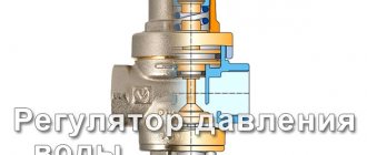
The choice of a water pressure regulator in a water supply system in a private house or apartment must be taken very seriously and during installation, comply with all requirements from the manufacturers. The water reducer plays an important role in the water supply and heating system.
Sometimes it becomes necessary to regulate it. If this operation is not performed, the system may fail, and further lead to unnecessary waste of time and money.
First of all, we will talk about installing and repairing a water pressure regulator. Below you will find information about popular control valve companies.
What are the most common regulator failures?
Failures are easily identified. They can be identified using the following signs:
- the pressure before and after the valve is the same or gradually increases;
- inability to adjust equipment;
- low network capacity – poor water pressure;
- presence of extraneous noise;
- presence of device leakage.
In most cases, the reason lies in a violation of the seal, which can be caused by wear of the o-rings. Limestone scale also prevents the spool from fitting tightly to the body.
Situations in which mechanical destruction of the structure occurs are more rare . These include: a burst spring or its thinning, disconnection of the lower piston from the spool rod or diaphragm rupture.
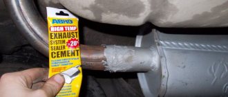
Oil pump pressure reducing valve failure - repair or replacement?
Repair work begins with disassembling the pressure reducing valve. Removing the cover and removing the spring is not difficult, but removing the valve itself usually becomes difficult. In order to do this, you will need the following tools:
- anchor bolt M8 (length 90 mm);
- nut for wrench 10;
- open-end wrench.
The anchor must be inserted tightly into the plunger, and then the nut must be screwed onto it. After this, take the wrench and continue tightening the nut. After some time, the piston will break off and you can remove it.
In the absence of the above tools, some craftsmen come up with their own ways of dismantling the valve.
Video: how to remove the valve using a wooden stick
The repair of this mechanism itself depends on the cause of the breakdown. If the problem was low pressure, you should replace the spring. It is very important to find the same part that was before. Please note that the sizes of pressure reducing valves and their components differ for different car models. We recommend that you consult with a specialist before purchasing the part, and come to the store with a disassembled mechanism.
If the valve becomes clogged and stops reducing pressure inside the oil pump, carry out the following procedures.
- Clean the part thoroughly, paying particular attention to the oil passages.
- Wash the mechanism in gasoline.
- Lubricate the dried part.
- Place the valve in its place.
- Now you need to check the pressure. For this, a conventional pressure gauge is used. The hose with a threaded fitting must be screwed into place of the standard pressure sensor, and then start the engine. You need to find out the values acceptable for your car in the engine manual. For most cars they range from 1 to 4.5 kg/cm2 at medium speeds.
Typically, experts recommend replacing the valve if major repairs have been carried out before. It is believed that ordinary cleaning and rinsing cannot cope with small chips. It is also worth replacing if you find mechanical damage on the surface of one of the valve components.
Repairing and replacing the pressure relief valve affects the overall performance of the vehicle. And this is not only clearly visible, but also clearly audible while the engine is running.
Which ones can you eliminate on your own and which ones can’t?
The vast majority of malfunctions occur due to hard water and the presence of limestone impurities in it. The more mineralized the water, the faster the pressure reducers begin to fail.
However, this difficulty can be easily resolved. The device can be quickly disassembled, cleaned, gaskets or O-rings replaced, and it will work as good as new.
There are not so many irreparable breakdowns. Mainly these are mechanical defects of the body and internal filling. These include the breakage of a spring or rod, as well as cavitation destruction of the seat and the walls of the gearbox.
Cavitation needs some explanation . This phenomenon occurs when the control device is chosen incorrectly, namely, its flow characteristics do not correspond to a particular pipeline.
If the regulator is noisy during operation, then this is the first sign of cavitation and that it must be changed.
Cavitation processes occur when the spool is almost always in a half-closed state - the cross-section of the manifold is minimal. In this position, an area of increased pressure appears in the connecting manifold.
Under such conditions, all the prerequisites for the chemical decomposition of the metal begin to arise. It actively destroys the seat for the spool - the contact of the piston becomes loose.
As plumbers put it, the fittings begin to mercilessly cut, i.e. she starts missing. It is very difficult, if not impossible, to correct this defect on your own - most often a complete replacement is required.
To prevent this from happening, you need to adhere to one rule - do not reduce the pressure in the pipeline with one reducer by more than 2.5 times. If this cannot be done, then the “cascade” method must be used, i.e. use two step-down devices.
Thus, a reduction from 10 to 3 atmospheres with one unit cannot be done without violating this rule . Then you need to use 2 devices - the first will reduce from 10 to 6 atm., and the second from 6 to 3. In this case, the risk of cavitation and noise generation will be guaranteed to be eliminated.
Oil pump pressure reducing valve - what is it and what is it for?
A car engine cannot function normally without constant lubrication with engine oil: parts will heat up from excessive friction and quickly become unusable. In order to ensure constant lubrication of all necessary elements, a design such as an oil pump was developed. It is he who is responsible for the supply and distribution of the lubricant.
However, here you need to pay attention to one important point: if the oil flowed freely, solely under the influence of gravity, many remote and hard-to-reach parts would not receive their share of lubrication and would run dry. On the other hand, too much pressure inside the pump would also increase wear on a number of elements. Oil seals and gaskets especially suffer from this, because due to the strong flow pressure they become thinner and begin to leak oil through themselves.
From all of the above, it is easy to conclude that the oil pump needs a special device responsible for maintaining stable pressure inside the system. Based on this feature, all pumps are divided into two categories:
The first type regulates pressure by changing the position of a certain part of the pump. But in the second, this function is performed by a pressure reducing valve. This is what we will talk about in more detail.
Reduction (from lat. reductio return bringing back) - simplification, reduction of the complex to something simpler, more visible, understandable, more accessible for analysis or solution; decrease, weakening of something.
Big Encyclopedic Dictionary
As the name of this device suggests, the main purpose of the pressure reducing valve is to normalize the pressure inside the oil pump system. That is, it reduces or increases pressure at the right time.
Reducing valve location
The oil pump itself is hidden under the hood of the car. To find out where your pump is located, check your vehicle's owner's manual, as the relative positions of the elements may vary depending on the make and model. For example, in a number of VAZ cars it is located behind the crankshaft pulley, so it is not immediately noticeable. As for the regulator, there are two options for the location of the device:
When located externally, the valve has its own body, which is located on the oil line. And with an internal pressure regulator, it is located directly inside the pump.
Design and principle of operation of a pressure reducing valve
The pressure reducing valve has a fairly simple structure. It consists of the following parts:
- ball (element No. 1 in the figure);
- spring (No. 2);
- thrust bolt (No. 3).
This device allows the valve to move, opening and closing the flow into the system under the influence of pressure. All elements are located inside a protective casing, which also has channels for the circulation of the lubricant.
The operating principle of this mechanism is to maintain the required pressure inside the pumping system. When it becomes significantly higher than the permissible level, the oil acts on the thrust bolt, which compresses the spring. The valve is squeezed out and an additional channel opens, through which excess oil is discharged into a special tank.
When the pressure returns to normal, the spring and valve return to their place, and the pump continues to function as usual. In this way, it is possible to regulate the flow rate and pressure of the oil supplied to lubricate the internal combustion engine.
Is there a difference in repairing a part installed in an apartment and in a private house?
Due to the fact that both the first and second use the same regulators, their repair is no different.
The only difference between the internal water supply networks of private houses and apartments is the number of plumbing fixtures and the length of the pipeline.
If in apartments there is no difficulty in draining water from the system, then in private households the situation is somewhat more complicated . Therefore, it is recommended to shut off control valves and filters with shut-off valves.
In all other respects, repair and prevention actions are no different.
Why do you need to monitor the pressure in the boiler?
The operation of the boiler is accompanied by changes in pressure in the circuit, which should be kept within established limits. This means that when the boiler is turned on, the pressure gauge must show a minimum bar value, and during operation the pressure cannot exceed the permissible level. Thus, three types of pressure are defined:
- dynamic pressure is the magnitude of the coolant voltage circulating in the heating circuit;
- static pressure - measured at idle and determines the load exerted by the coolant on the heating circuit;
- maximum pressure is the permissible load limit at which normal operation of the system is allowed.
If the pressure in the gas boiler increases, the consequence is that the normal operation of the system ceases; water is periodically released through the relief valve or from the expansion tank.
What are the causes of malfunctions, how to repair them yourself?
Let's look at the main malfunctions, their causes, and how to eliminate them. But first, let's look at the procedure for dismantling the gearbox - the differences between disassembling the membrane and piston variations are not significant.
It is not necessary to completely remove the regulator, but it is recommended in cases where it is necessary to clean and (or) grind the spool seat:
First you need to loosen the spring - unscrew the clamp and the adjusting nut counterclockwise.
A wide or thin slotted screwdriver, open-end wrench or hex can be used.- Unscrew the housing cover and take out the spring - this is access to the membrane fastener or piston pulley.
- Remove the plug or pressure gauge to gain access to the spool mount.
- Remove the internal filling and unscrew both nuts at the same time: on the piston or membrane side and on the spool side. The fasteners differ on different models - you need the appropriate tools.
- Start preventative or repair measures.
- Reassemble in reverse order.
Open all the time
This problem can be expressed differently - the pressure after the regulator is steadily increasing, tending to the value of the inlet pressure.
Reasons and what to do:
- The valve disc (piston) does not fit tightly to the spool seat, which means dirt gets on your face or scale forms in the area of the seat on the piston or membrane. Required: perform routine maintenance of the pressure reduction valve: remove scale and dirt (the use of abrasives is not permissible, only alkaline or alcohol solutions).
- The piston moves freely in the seat - the sealing ring is worn out. Required: Replacement of the stop valve O-ring.
- Uneven abrasion of the sealing elements is caused by an incorrect choice of installation position of the gearbox: the piston stroke occurs in a horizontal plane, mineral deposits settle and damage the lower part of the sealing element.
Permanently closed
A complete lack of water pressure can occur only in two cases:
Incorrect installation of the pressure reducer - the problem of lack of pressure occurs immediately after installation.
The connection of the input and output pipes is mixed up. The hardware needs to be reinstalled.- The shut-off valve is stuck in the “Closed” position, which occurs after a long break in the operation of the internal water supply network. Mineral deposits settle and coke the spool with the seat.
The mechanism must be completely disassembled and cleaned. The use of abrasives is strictly prohibited - only alcohol, anti-corrosion or other alkaline agents. If necessary, all sealing elements must be replaced.
The rod is stuck
This malfunction occurs during a long interruption in the operation of the water supply network, both full and empty. When the system is full, the valve will jam in the “Closed” state, and when dehydrated, it will stick in the “Open” state.
To bring the device into working condition, complete disassembly and cleaning is required. Seals may need to be replaced.
Flowing
Leakage is the main failure of regulators. Occurs due to a seal failure:
- for piston engines - an o-ring on the large piston,
- for membrane ones - dirt gets between the diaphragm and the seat.
It can be eliminated by washing the housing, seal seats, treating the cylinders with grinding pastes and replacing the O-rings.
If there is a leak from under the plug, replace the O-ring and seal the threads of the plug with fume tape or plumber's flax with sealant.
The device does not affect pressure changes
If the static pressure “after” is kept in one position or changes slightly (without tending to the inlet pressure), then this means that:
- the rod is stuck or jammed;
- the spring broke - unlikely, but it happens in the absence of maintenance, when the metal is weakened by rust.
There are cases when the adjustment is unstable, i.e. the pressure fluctuates:
- The most common pressure surges are due to incorrect selection of the gearbox, when its throughput is significantly higher than the nominal value of the internal network - the valve is in the “Almost Closed” state. In addition to the fact that it is very difficult to set the pressure, the regulator makes a lot of noise in such a situation - due to increased destruction of the spool seat, the service life is minimal.
- Pressure surges do not always occur, but can occur in the absence of a calming gap in the pipeline. To eliminate the possibility of this defect, it is recommended to form straight sections after the gearbox that are at least 5 times the diameter of the pipe being used.
Membrane rupture
If the membrane fails due to its rupture, the following consequences are guaranteed:
- gearbox leak;
- the device is always in the “Closed” state or low pressure.
To correct the breakdown, replacement of this element is required.
Malfunctions in the operation of the pressure reducing valve
The structure of the pressure reducing valve is quite simple, which ensures its reliability and reduces the likelihood of breakdown. However, sometimes this still happens. Most often this is due to wear and tear of the mechanism, so do not forget to regularly diagnose all components of the car, as well as promptly replace outdated parts.
There are two main types of mechanism failure.
- The valve creates insufficient pressure. Usually the cause of this problem lies in the spring. With prolonged use, it becomes less elastic and stretches. As a result, the valve remains slightly open all the time. Due to this, the pressure decreases, and the oil does not reach some engine components. Sometimes it happens that unprofessional craftsmen install a spring with insufficient elasticity during repairs. This has the same effect.
- Excessive pressure builds up in the valve. As a rule, the cause of this breakdown is the entry of debris into the mechanism or the use of old viscous oil.
How to determine that the pressure relief valve is broken?
It is impossible to determine at first glance that the valve is broken. It is necessary to carefully inspect other elements of the system and exclude the possibility of damage to other parts of the oil pump. In order to understand that there are malfunctions in it, you should look at the dashboard. Most car models have a sensor located there that indicates problems in the system. It is a warning light with a pictogram that lights up at high speeds.
If this happens, you should stop the car immediately, as further movement may lead to permanent engine damage. Turn it off and get out of the car. Next, you will need to take the following steps.
- Wear protective gloves. At the moment, the engine compartment of the car is hot, so you can easily get burned.
- There is no point in checking the oil level if you have just stopped. It will take time before it drains into the crankcase. At this time, you need to inspect the engine: look for fresh oil leaks or damage to the crankcase.
- If the problem is a broken crankcase, you will need to seal it. This can be done using available materials: an ordinary rag, a piece of rubber and even tape.
- Inspect the oil filter. Damage to its gasket can also cause a breakdown.
- If the above items are in order, you should check the oil level. This is done with a special probe with o and “maximum”. Ideally, the oil level should be between them. If there is a lack of lubricant, simply add it.
All further actions are carried out on the valve removed from the pumping system. Examine it carefully. Often the cause of breakdown is clogging of the mechanism. This usually happens to drivers who are too lazy to change the oil. Dirt accumulates on the surface of the valve or spring, which prevents normal operation. If you have recently carried out a major overhaul of your car, then there is a risk that the valve was not properly washed and there are particles of chips and other debris left in it.
For this reason, technicians often recommend replacing valves after major repairs. If you do not want to do this, make sure that the system is not clogged before using the vehicle.
There is an unusual way to check the functionality of this element. Take a small piece of cotton (or other breathable) fabric and place it on the fitting that is parallel to the lid. Now you need to take a sharp breath through the material. If you feel strong resistance, it means that the valve is working as it should: it blocks the air flow and passes it through a special hole. A working mechanism should not be easily blown through.
Table: diagnosis of low pressure in the oil pump, causes and remedy
| Guide to diagnosing hypotension | ||
| Malfunction | Cause | Remedy |
|
|
|
| Low oil pressure throughout the entire engine speed range | There is too little oil in the engine. The oil intake screen is dirty, the oil intake tube is broken | Add oil to the engine. Remove the oil sump, clean the mesh, if necessary, replace the tube. |
| Worn oil pump | Remove, check, replace if necessary | |
| Engine bearing wear | Repair the engine | |
Preventing problems
It is impossible to completely eliminate all factors that reduce the continuous service life. However, if you take preventive measures, you can significantly increase it:
The weak point of piston gearboxes is their moving mechanism - sealing elements.
To increase their service life, they are treated with graphite lubricant. Also for this purpose, the cylinder is ground under the spool - this helps eliminate burrs and roughness, which reduces the production of rubber gaskets.- Perform routine maintenance once or twice a year. Disassembly, cleaning and reassembly will not take much time, but will avoid the formation of equipment leaks and stabilize pressure regulation.
- Water hammer is the scourge of all plumbing fixtures. Pressure regulators are capable of extinguishing these short-term pressure surges, but they have an extremely negative attitude towards them - if the internal structural elements are made of polymer plastic, then even the risk of complete failure of the product cannot be excluded. To eliminate negative consequences, it is recommended to equip the water supply network with a check valve and (or) a membrane water hammer absorber.
Design features
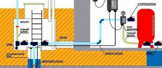
The main tasks that water flow control sensors installed in domestic pipelines solve are to turn off pumping equipment at a time when there is no liquid in the system or its flow pressure exceeds the standard value, and turn it on again when the pressure drops. An effective solution to these important problems is provided by the sensor design, which consists of the following elements:
- a pipe through which water enters the sensor;
- a membrane that makes up one of the walls of the inner chamber of the sensor;
- a reed switch that provides closing and opening of the pump power supply circuit;
- two springs of different diameters (the degree of their compression regulates the pressure of the fluid flow, at which the water flow switch for the pump will operate).
Main components of an industrial flow sensor
The device of the above-described design works as follows:
- Entering the inner chamber of the sensor, the water flow puts pressure on the membrane, displacing it.
- The magnetic element fixed on the back side of the membrane, when it is displaced, approaches the reed switch, which leads to the closure of its contacts and the pump being turned on.
- If the pressure of the water flow passing through the sensor drops, the membrane returns to its original position, the magnet moves away from the switch, its contacts open, and accordingly, the pumping unit is turned off.
The operating principle of a flow sensor based on a permanent magnet and a reed switch
Sensors that monitor water flow are installed quite simply in pipeline systems for various purposes.
The main thing is to choose the right device, paying attention to its operating parameters and characteristics of the pumping equipment
Why does pressure drop in the storage tank?
Most likely, the pressure decreases due to an air leak. The reason is in the pressure line itself. Repair of an electric compressor consists of a thorough inspection of the pipeline. To do this, prepare a soap emulsion and coat the joints in the pipeline. If a leak is found, it is treated with sealing tape.
The receiver's outlet valve is capable of letting air through when it is not tightly screwed on or has become unusable.
The piston head of the compressor is equipped with a control valve, which can also cause defective operation of the device. The cylinder head is disassembled, but the air is first released from the accumulator. If such an operation does not help, the valve must be replaced.
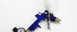
Top 3 gearbox models
From the point of view of design features, devices are not divided into apartments and for private buildings. They are selected based on:
- power;
- cost;
- durability;
- number of consumers;
- required pressure.
Here is an overview of the top models.
For apartment
Give preference to the following models - they work optimally in apartment conditions:
- WATTS DRVN - small capacity, good pressure gauge location, functional pressure adjustment knob. High wear resistance;
- CALEFFI 5330 - equipped with a replaceable filter and cartridge. Made from brass. Durable. Has a setting key. Easy to maintain and repair. It is manufactured in two versions - with and without a pressure gauge. The weak point is the pressure control mechanism;
- VALTEK is a domestically assembled product. Parts are purchased from Italian partners. Small dimensions against the backdrop of excellent functionality of the device. The downside is that there is a risk of getting a Chinese counterfeit.
For a private home
The best options in terms of price and quality:
- Honeywell D04FM-¾A is a universal membrane type model. Has wiring for installing a pressure gauge. The body is made of brass - a durable and strong material. Adapted for cold and hot water, allows you to independently regulate the pressure in the pipes, has a double thread. The weak point is the membrane. If the pressure is adjusted carelessly, it may break;
- Honeywell D06FM is an upgraded analogue of the previous version. Comes with a built-in filter. Available in two modifications - brass or polymer flask. The pressure is adjusted without using a pressure gauge. The downside is that the settings need to be constantly updated. Price - from 4.5 thousand rubles;
- OR0232 and OR0233 are piston types of gearboxes. Small in size, but quite powerful devices. The pressure gauge can be connected both from below and from above. Suitable for all types of pipelines. Disadvantage: horizontal installation of the product is not provided.
When should you adjust or remove default settings?
The input power does not always correspond to the standard 5.0 - 6.0 bar. If the pressure in the supply network differs significantly from the standard, then the water pressure after the reducer will be different from the factory settings.
As an example, consider a regulator set to 3.0 bar with an inlet pressure of 5.0 bar. That is, a difference of 2.0 bar.
If the input pressure is 2.5 bar, then the output value will be only 0.5 bar, which is very small for normal use. Some setup will be required.
If the input pressure is 7.0 bar, then the output value will be 5.0 bar, which is very high. Some setup will be required.
Deviation from standards may occur under the following conditions:
- water consumption significantly exceeds the capacity of central networks and pumping stations, the pressure will be low;
- upper floors of tall buildings, low pressure;
- the lower floors of tall buildings, the pressure will be high;
- Incorrect operation of the booster pumps in the building; the pressure may be low or too high.
In such situations, it is necessary to reconfigure the gearbox. A change in inlet water pressure can also occur during long-term operation of water supply networks. Including due to a decrease in the flow area of pipes in the building due to the formation of deposits and corrosion.
Adjustment may be required more than once during prolonged use of water.
Gearboxes are subject to wear, leading to water leakage. They can be repaired, which requires disassembly. After assembling the device, it will need to be adjusted.
Connection diagram
Pressure switches for compressors can be for different load connection schemes. For a single-phase engine, a 220-volt relay is used, with two groups of connections. If we have three phases, then install a 380-volt device that has three electronic contacts for all three phases. For a three-phase motor, you should not use a relay for a 220-volt compressor, because one phase cannot be switched off from the load.
Flanges
The device may include additional connection flanges. Usually equipped with no more than three flanges, with a hole size of 1/4 inch. Thanks to this, you can connect additional parts to the compressor, for example, a pressure gauge or a safety valve.
Connecting a pressure switch
Relay installation
Let us turn to the issue of connecting and adjusting the relay. How to connect a relay:
- We connect the device to the receiver via the main output.
- If necessary, connect a pressure gauge if there are flanges.
- If necessary, we also connect a relief and safety valve to the flanges.
- Channels that are not used must be closed with plugs.
- Connect the electric motor control circuit to the pressure switch contacts.
- The current consumed by the motor should not be higher than the voltage of the pressure switch contacts. Motors with low power can be installed directly, and with high power, the required magnetic starter is installed.
- Adjust the parameters of the highest and lowest pressure in the system using the adjusting screws.
The compressor relay should be adjusted under pressure, but with the engine power supply turned off.
When replacing or connecting a relay, you should know the exact voltage in the network: 220 or 380 volts
Relay adjustment
The pressure switch is usually sold already configured and adjusted by the manufacturer, and does not require additional adjustments. But sometimes it becomes necessary to change the factory settings. First you need to know the compressor parameter range. Using a pressure gauge, the pressure at which the relay turns the motor on or off is determined.
After determining the required values, the compressor is disconnected from the network. Then remove the relay cover. Underneath there are two bolts of slightly different sizes. Using the larger bolt, the maximum pressure is adjusted when the engine should be turned off. It is usually denoted by the letter P and an arrow with a plus or minus. To increase the value of this parameter, turn the screw towards “plus”, and to decrease – towards “minus”.
The smaller screw sets the difference between the on and off pressures. Indicated by the symbol “ΔΡ” and an arrow. Usually the difference is set at 1.5-2 bar. The higher this indicator, the less often the relay turns on the engine, but at the same time the pressure drop in the system will increase.
Why is it necessary to replace the water pressure reducer and what is its price?
A water pressure reducer (or regulator) is a device that automatically regulates the pressure of the water flow. Its main purpose is considered to be the protection of devices from water hammer and surges in water pressure, which can damage plumbing fixtures.
How can you change it if necessary? Read the article about the nuances and cost of replacing a water pressure reducer in an apartment.
Who should change - the management company or the owner?
In order to understand this issue, it is necessary to consider where the gearbox is located.
As a rule, it is installed between the filter and the H2O flow meter (installation after the meter is also allowed), i.e. after the first locking device on the apartment outlet.
According to the rules for the operation of common property (Resolution of the Government of the Russian Federation No. 491 of August 13, 2006), all devices, pipelines and other devices installed after the first element of the shut-off valves are the property of the apartment owner and are at his full disposal.
Manufacturers
Among the leading manufacturers of gearboxes, Italian companies predominate. They are traditionally famous among manufacturers of such products. However, the Russian company Valtec or the American Honeywell are no less famous.
To more clearly compare products from different manufacturers, let's create a table:
| Brand | Pressure (max) | Temperature (max) | Setting limits (Bar) | Pressure gauge | Adjustment type |
| Valtec | 16 At | 40° — 70° | 1,5-6 | Eat | Pen |
| Honeywell | 25 At | 40° — 70° | 1,5-6 | Eat | Pen |
| Watts | 10 At | 30° | 1-6 | Eat | Pen |
| Herz | 10 At | 40° | 1-6 | Eat | Pen |
| Caleffi | 10 At | 80° | 1-6 | Eat | Pen |
| Giacomini | 16 At | 130° | 1-5,5 | Eat | Pen |
Looking at the table, you can see that the parameters of all household devices are more or less similar. Only the maximum temperature and operating pressure differ. This makes it easier for users to choose the right device.