The steepness of a slope is the ratio of the depth of a pit (trench or other excavation) to its location (projection of the slope onto a horizontal plane). The steepness of the slopes of pits, trenches and other excavations is given in the following groups of regulatory documents:
Group I:
- SP 45.13330.2017 Earthworks, bases and foundations. Updated version of SNiP 3.02.01-87. (mandatory for use from August 1, 2022 according to Decree of the Government of the Russian Federation dated July 4, 2022 N 985)
- Rules for labor protection during construction, reconstruction and repair. Approved by order of the Ministry of Labor of Russia No. 883n dated December 11, 2022 (valid from 01/01/2021)
- Rules for labor protection in construction. Approved by Order of the Ministry of Labor of Russia N 336n dated June 1, 2015 (valid until 01/01/2021)
Group II:
- SP 45.13330.2012 Earthworks, bases and foundations. Updated version of SNiP 3.02.01-87. (valid and mandatory until August 1, 2022 for use in accordance with Decree of the Government of the Russian Federation dated December 26, 2014 N 1521
- SNiP 12-04-2002 “Labor safety in construction. Part 2. Construction production" (advisory)
Let us highlight the requirements given in these documents, which directly relate to the magnitude of the steepness of the slopes.
Excavation plan, requirements for them
Excavation work takes place in a number of stages. They are prescribed in SNiP 3.02.01-87. The main stages of the process are as follows:
- carrying out preparatory activities;
- experimental production part;
- creating a pit or trench;
- carrying out control activities;
- acceptance of completed work.
SNiP 3.02.01-87 provides the following requirements:
- developing a working draft is allowed only by specialists who have the necessary qualifications and experience;
- communication and coordination of actions in matters of design, construction, and engineering solutions must be ensured between them;
- It is constantly necessary to monitor the quality of construction work on site;
- the project must be implemented by personnel with appropriate qualifications;
- the erected structure may only be used for its intended purpose in accordance with the design;
- Maintenance activities for the structure and accompanying utilities must maintain it in a safe, working condition throughout its operation.
When digging pits and trenches, you must adhere to the following instructions:
- rules for organizing their construction;
- standards for conducting geodetic work;
- labor protection standards;
- sections of fire safety rules relating to construction work.
Fenced construction site with fixed pit walls
Earthen structures must be created strictly according to the current design.
Carrying out work with explosives requires compliance with appropriate safety rules during their production.
The materials, structures, and products used in the work must meet the requirements of the standards and the project. Their replacement may be carried out only after prior agreement with the organization that developed the documentation and the customer.
The following types of control during excavation work are distinguished:
- input;
- operating;
- acceptance
Control is carried out in accordance with SP 48.13330.
Acceptance of work occurs with the preparation of the necessary documentation (acts) confirming its completion.
The considered requirements in individual construction are greatly simplified. Small buildings are often erected without any projects, and the depth of excavations does not exceed 1.5-2 m, but safety precautions must always be observed.
Step-by-step instructions for drawing a pit:
1. Draw a grid of extreme axes and the contour of the foundation pit.
2. We retreat 100 mm outward from the foundation contour, thereby obtaining a preparation contour.
3. We retreat 500 mm outward from the preparation contour - the permissible minimum before the start of the slope, specified by the standards (previously it was 300 mm). This will be the contour line of the bottom of the pit.
4. We retreat from the contour of the bottom of the pit by 2.33 m (the depth of the pit) - because slopes at an angle of 45 degrees, then the size of the slopes in plan is equal to the depth of the pit. This will be the line of the top of the slope. We apply a symbol for slopes on it in the form of alternating short and long lines perpendicular to the contour.
5. We remove all unnecessary lines (foundation, preparation contour), mark the bottom of the pit and mark the existing ground.
6. Apply the missing dimensions - linking the corners of the pit to the axes.
7. Add a note about the correspondence of relative marks to absolute ones.
8. If desired, we make a cut (we mark the marks and slopes of the slopes on it).
There is no need to develop the entrance to the pit, this is the concern of the PIC (construction organization project), i.e. separate money.
Example 2
. The same pit, only the soil has a slope in one direction (the absolute elevations of the existing land are shown in the figure below). The 0.000 mark in the project is conventionally taken to be 52.07. The bottom elevation of the foundation slab is -3,000. A preparation of 100 mm thick concrete is provided under the slab. The soil is loam, the slopes need to be made as steep as possible.
So, we have a ground drop in one direction - from 53.50 to 51.70 m, while the marks on the survey are indicated at specific points on the plan.
In such a situation, it is easier to start with a cut of the pit.
Let's convert the absolute marks we have into relative ones.
The absolute elevation of 53.50 m corresponds to the relative elevation of 53.50 – 52.07 = 1.430 m.
The absolute elevation of 51.70 m corresponds to the relative elevation of 51.70 – 52.07 = -0.370 m.
The elevation of the pit bottom is -3,100 m.
The easiest way to watch the pit construction algorithm will be on video.
As you can see, everything is not that complicated. And the drawing will ultimately look like this.
Many people never think about what kind of excavation work should be done, regardless of its purpose. But building your own home
without the development of land is almost unthinkable. Trenches for strip foundations, or drainage devices - all this excavation work must be carried out not only taking into account the technological requirements of the structures that will be laid in them, but also in compliance with safety standards. As practice shows, even the slightest disregard for compliance with the requirements regarding the width of the trench often leads to quite serious consequences, which could have been avoided quite simply.
How do most of us most often determine what it should be? To make it convenient to work below - this is the most common answer. Yes, the width of the trench in its lower part must meet this requirement, so it depends on the diameter of the pipeline that will be laid in the finished trench, as well as the method of laying the pipes.
- The outer diameter of the pipeline does not exceed 700 mm, and pipes are laid in ready-made sections. The optimal trench width in this case will consist of the pipeline diameter, to which 300 mm is added. In addition, there is a minimum limitation on the width of the trench, regardless of the diameter of the pipe, which must be at least 700 mm;
- If the diameter of the pipeline laid in sections exceeds 700 mm, the pipe diameter in the lower part should be increased by 1.5;
- If the pipeline will be installed with separate pipes whose diameter does not exceed 500 mm, the width of the bottom of the trench must correspond to the sum of the pipe diameter and 500 mm for steel pipes; diameter + 600 mm – for pipes made of different materials with a socket; diameter + 800 mm – for pipes connected using flanges or couplings.
Now you know how to determine the width of a trench based on the diameter of the pipeline laid in it. But often this is not enough. The fact is that the width of the trench in its upper part also depends on the type of soil in which the excavation work is carried out.
Trench slopes
Each type of soil has its own properties, which include the angle of natural collapse. This official formulation implies that at a significant depth of the trench, the soil can collapse due to insufficient adhesion of its particles, and the collapse zone for each type of soil is quite individual. Therefore, there is a table that shows the values of the permissible slope slopes of the trench
for the main types of soils, subject to which there is practically no risk of soil collapse.
Using this table, depending on its depth and type of soil, you can determine the optimal width of the trench
in its upper part.
Table of permissible slope steepness
I think this table requires some explanation. The angle of repose of each type of soil in this table is indicated relative to the lower horizontal surface of the trench, as shown in the diagram. In addition to the angle value, the ratio of the height of the slope to its horizontal projection is also indicated. Let's take, as an example, the situation with bulk soils, which are the most dangerous when performing excavation work due to the low adhesion force of its particles to each other.
With a trench depth of 1.5 meters, the angle of repose of the trench
according to the table should be 56°.
The distance from the point of intersection of the angle line with the ground surface to the beginning of the trench in this case is 1 meter, which has a ratio of 1:0.67. If the depth of 1.5 meters is multiplied by 0.67, we get 1.005 meters. It is at this distance that the slopes of the trench
from its supposed vertical walls, otherwise the risk of soil collapse is very high, and this means not only the loss of materials or repeated excavation work, but also a threat to your life or the lives of the workers working in the trench.
(Designation on the diagram: 1-soil; 2-possible collapse zone, which should be included in the slope; 3-theoretical size of the trench).
As can be seen from the table, the best in terms of adhesion of soil particles to each other are clay, loam and moraine loam. If your site has just such soils, you are in luck in this case. If you have mobile soils, in order not to turn deep trenches into pits, their vertical walls need to be strengthened. I will tell you how this is done in the next post.
Permissible steepness of slopes of trenches and pits
| Excavation depth, m | ||||||
| Characteristic | From 3.0 to 5.0 | |||||
| Angle between the direction of the slope and the horizontal, degrees. | The ratio of the height of the slope to its foundation | Angle between the direction of the slope and the horizontal, degrees. | The ratio of the height of the slope to its foundation | |||
| Bulk natural humidity | ||||||
| Sandy and gravelly wet but not saturated | ||||||
| Clayey natural moisture content: | ||||||
| loam | ||||||
| Loess-like dry | ||||||
Notes: 1. When the excavation depth is more than 5 m, the steepness of the slopes is established by calculation.
2. The steepness of slopes in waterlogged soils should be reduced against the values indicated in the table to 1:1 (45°).
3. It is prohibited to develop waterlogged, sandy, loess-like and bulk soils without supports.
20.8. The vertical walls of trenches and pits must be secured with shields in accordance with the instructions given in Table 15.
Table 15
Fastening the walls of pits and trenches depending on the soil
| Types of vertical fastenings walls of pits and trenches | |
| Natural moisture, excluding bulk | Horizontal fastening with clearance through one board |
| High humidity and loose | Solid vertical or horizontal mounting |
| All types with a strong influx of groundwater | Sheet piling below the groundwater horizon with its driving to a depth of at least 0.75 m into the underlying waterproof soil |
20.9. The fastening of pits and trenches up to 3 m deep, as a rule, must be inventive and carried out according to standard designs. In the absence of inventory and standard parts for fastening pits and trenches up to 3 m deep, you should:
20.9.1. Use boards with a thickness of at least 4 cm in sandy and high-humidity soils, laying them behind vertical posts as they go deeper;
20.9.2. Install fastening posts at least every 1.5 m;
20.9.3. Place spacers at a vertical distance of no more than 1 m from one another; nail bosses under the ends of the spacers (top and bottom);
20.9.4. Extend the upper fastening boards above the edges of the recesses by at least 15 cm;
20.9.5. Strengthen the fastenings (spacers) on which the shelves intended for transferring soil rest, and protect these shelves with side boards at least 15 cm high.
20.10. Fastening the vertical walls of pits and trenches with a depth of more than 3 m should, as a rule, be carried out according to individual projects.
20.11. Dismantling of fasteners must be carried out under the direct supervision of the Responsible Workman.
Dismantling should be done from the bottom up as the soil is backfilled.
20.12. When performing excavation work, it is necessary to ensure systematic monitoring of the condition of the soil in trenches and pits.
20.13. If large stones are found on slopes, workers must be removed from dangerous places, and the stones must be lowered to the bottom of the slope or removed.
20.14. Chambers and sections of underground heating pipelines opened for work must be covered with strong and dense shields or fenced.
20.15. Through trenches and pits dug on platforms, driveways, passages and other places where people move, passages with a width of at least 0.7 m should be constructed, fenced on both sides with railings at least 1 m high with lining along the bottom of the sides at least 10 cm wide. .
20.16. You should only go down into trenches and pits using ladders.
20.17. If there are electrical cables in excavation sites, you cannot use impact tools: a crowbar, a pick, pneumatic shovels, etc. Work should be carried out in the presence of a cable network worker, taking care to prevent damage to the cable and electric shock to workers.
20.18. When the cable is exposed, it is necessary to hang it to avoid breaking; standing on the cable is strictly prohibited. If the work is long, the cable must be sewn into a wooden box. Posters should be posted on the boxes covering the excavated cables: “Stop: high voltage” or “Stop: dangerous to life.”
20.19. Throwing tools or materials into the pit is prohibited. It must be lowered on a rope or passed from hand to hand. It is prohibited to stand under the load being lowered into the pit.
20.20. If the smell of gas is detected during excavation work, the work must be stopped immediately and workers removed from dangerous places until the causes of the gas are identified and eliminated.
Further work in the event of the possibility of gas occurrence is allowed only if constant monitoring of the state of the air environment is ensured and workers are provided with the necessary number of gas masks.
In this case, before starting work, workers must be instructed on the procedure for carrying out work in a gas-contaminated area.
20.21. To avoid an explosion, smoking, working with a blowtorch or other devices involving the use of open fire is prohibited in trenches near which there is a gas pipeline or where gas may accumulate.
20.22. Areas where electrical heating of the soil is carried out must be fenced, and warning signals must be hung on the fences. At night, the heated area should be illuminated.
For electrical heating of soil with natural humidity, a voltage of no more than 380 V is allowed.
20.23. Unauthorized persons are prohibited from staying in energized areas.
Electric heating must be serviced by an electrician with the appropriate qualification group.
20.24. Temporary lines from the transformer to the heated areas must be made with insulated wire of the appropriate cross-section, laid on trestles with a height of at least 0.5 m from the ground.
20.25. When the soil is heated by flue gases, hot water or steaming, measures must be taken to protect workers from burns.
20.26. When surface thawing of soil using hot gas, it is necessary to take measures to prevent poisoning of workers and a gas explosion.
20.27. The organization that carries out the work is responsible for the safety of work carried out on the route of existing heating networks, and this work is allowed to be carried out only after agreement with the organization that operates or owns these networks.
21. SAFETY REQUIREMENTS FOR HANDLING SOURCES OF IONIZING RADIATION
21.1. Work with radioactive substances and sources of ionizing radiation is carried out with the permission and under the control of the state nuclear and sanitary supervision bodies, which must be provided with all the necessary documentation about the nature of the work being carried out, the radiation situation in the organization and in the adjacent territory.
21.2. Radioactive isotopes used in production are sources of various types of radiation that have a harmful effect on the human body. As a result of ionization of adipose tissue, which consists of 70% water, molecular bonds are broken and the chemical structure of various compounds changes, which leads to cell death.
21.3. The nature of the damaging effect of radioactive radiation depends on a number of conditions: the type of radiation (-, -, -, neutron radiation), its activity and energy, the lifetime of the isotope (half-life), internal or external irradiation, irradiation time, etc. .
21.4. The main task of radiation safety, which ensures the protection of people from the harmful effects of ionizing radiation, is to exclude any unnecessary exposure; reducing the radiation dose to the lowest possible level and not exceeding the established basic limit. The main document regulating the levels of exposure to ionizing radiation on humans is NRB-96.
21.5. The following categories of exposed persons are established according to the permissible basic dose limits:
Table 16
GN 2.6.1.054-96
Basic dose limits
| Standardized values | Dose limits | |
| Personnel* (Group A) | Members of the public | |
| Effective dose | 20 mSv*** per year on average for any consecutive 5 years, but not more than 50 mSv per year | 1 mSv per year on average for any consecutive 5 years, but not more than 5 mSv per year |
| Equivalent dose per year in the lens | ||
| bones and feet | ||
* - radiation doses, like all other permissible derived levels for group B personnel, should not exceed
1/4 of the values for group A personnel;
** - refers to the average value in a layer 5 mg/cm2
thick . On the palms, the thickness of the coating layer is 40 mg/ cm2 ;
***- 1 mSv (millisievert) = 100 mrem (milirem);
One Sievert (Sv), which is the SI unit of equivalent dose, is equal to the equivalent dose at which the product of the absorbed dose in biological tissue and the average quality factor K (K = 1 - for beta particles and gamma radiation; K = 3 - for neutrons with energy less than 0.03 MeV; K=10 - for neutrons with energy 0.03-100 MeV (fast neutrons); K=20 - for alpha particles) is equal to 1 J/kg.
21.5.2. The entire population, including personnel, is outside the scope and conditions of their production activities.
21.6. Permissible radioactive contamination of working surfaces, leather, work clothes, safety shoes, and personal protective equipment for personnel are given in Table 17.
Table 17
GN 2.6.1.054-96
Permissible levels of general radioactive contamination of working surfaces and skin
(during the work shift), workwear and personal protective equipment, part/(min*cm 2)
| Object of pollution | Alpha active nuclides | Betta active | |
| separate | |||
| 1. Intact skin, special underwear, towels, the inner surface of the front parts of personal protective equipment | |||
| 2. Basic workwear, the inner surface of additional personal protective equipment, the outer surface of safety shoes | |||
| 3. Surfaces of permanent premises for personnel and equipment located in them | |||
| 4. Surfaces of premises for periodic stay of personnel and equipment located in them | |||
| 5. The outer surface of additional personal protective equipment removed in sanitary locks | |||
21.7. When using sources of ionizing radiation in work, the employer is obliged to ensure the radiation safety of these works and organize monitoring of the condition and ensuring radiation safety.
21.8. The administration of an organization that uses sources of ionizing radiation in its work is obliged, taking into account the specifics of the work carried out with the sources, to coordinate with the local authorities of state nuclear inspection and sanitary and epidemiological supervision and approve the regulations on the radiation safety service of the organization.
21.9. The objectives of the organization’s radiation safety service should be:
monitoring compliance with rules, regulations and radiation safety requirements;
control over the condition, accounting, storage, receipt, issue, transportation and use of sources of ionizing radiation;
control over personnel radiation doses;
control over the admission of personnel to work with sources of ionizing radiation, training and instruction of personnel;
control over emissions into the environment and the general radiation background in the organization, over the level of radiation contamination of premises, equipment, protective clothing and other personal protective equipment, skin, clothing of personnel, the quality of their decontamination, etc.;
providing the organization's administration with the necessary information about the state of radiation safety in the organization;
control over all types of work with sources of ionizing radiation;
control over compliance with radiation safety requirements in relation to products manufactured by the organization, etc.
21.10. Radiation safety service workers must be from among the personnel directly working with sources of ionizing radiation (category A), must have an appropriate certificate of special training, and be proficient in control and measurement methods to the extent necessary to perform their functions.
21.11. In its work, the radiation safety service must be guided by current legislation and regulations on radiation safety.
21.12. Instructions and instructions from the organization's radiation safety service to eliminate identified violations are mandatory for execution within the time limits established by the chief engineer (technical director).
21.13. The employer is responsible for the state of radiation safety in the organization.
21.14. The main methods of protection against ionizing radiation are:
protection by distance (the radiation intensity decreases in proportion to the square of the distance), therefore remote control should be used when working with sources of ionizing radiation;
time protection (reducing the time of contact with a source of ionizing radiation), therefore work must be carried out in a strictly organized manner within a compressed time frame;
protection by shielding (sheltering a source of ionizing radiation in containers and other structures made of materials that absorb radiation well (lead, concrete, glass and other materials)).
21.15. When working with ampoules containing radioactive substances, external irradiation is possible. Therefore, working with ampoules requires special radiation protection measures.
21.16. In emergency cases, when the integrity of the ampoule may be compromised, special measures must be taken, including fencing off the dangerous area with radiation hazard signs, beyond which the radiation power does not exceed the permissible limit.
21.17. Particular attention in the organization should be paid to the storage and transportation of sources of ionizing radiation. Such substances are transported in lead containers on special vehicles equipped with radiation hazard signs.
21.18. Persons at least 18 years of age who have undergone appropriate training, medical examination and radiation monitoring may be allowed to work with radioactive isotopes.
21.19.
The nature and organization of radiation monitoring depend on the type of work performed. Radiometers monitor the level of cleanliness of workers’ hands, clothes and bodies and work surfaces. Dosimeters determine the dose or dose rate of radiation in roentgens or rem. The results of dosimetric monitoring must be recorded in special journals and radiation dose cards, which must be entered for each employee working in contact with sources of ionizing radiation. danger
_
Organization of the event
.
POT RO 14000
-
005
-
98
Approved. Department of Economics and Mechanical Engineering of the Ministry of Economy...
As a result of excavation work, earthworks are created, which are classified according to a number of characteristics.
According to their purpose and duration of operation, earthen structures are divided into permanent and temporary.
Permanent structures are designed for long-term use. These include canals, dams, dams, planned sites for residential areas, complexes of industrial buildings, stadiums, airfields, excavation and embankment of road subgrades, construction of reservoirs, etc.
Temporary earthworks are those that are erected only for the construction period. They are intended for placing technical equipment and performing construction and installation work on the construction of foundations and underground parts of buildings, laying underground communications, etc.
A temporary excavation with a width of up to 3 m and a length significantly exceeding the width is called a trench. A recess whose length is equal to the width or does not exceed ten times its value is called a pit. Pits and trenches have a bottom and side surfaces, inclined slopes or vertical walls.
The division of earthworks into permanent and temporary is necessary, since they are subject to different requirements regarding the stability of slopes, the thoroughness of their compaction and finishing, and ensuring the waterproofness of the excavation body.
According to the location of earthen structures relative to the surface of the earth, they differ: excavations - depressions formed by the development of soil below the surface level; embankments - elevations on the surface, erected by dumping previously developed soil; Cavaliers are embankments formed when dumping unnecessary soil, as well as for temporary storage of soil, backfilling of trenches and foundations.
The most typical profiles and elements of earthworks are presented in Fig. 1.1.
Rice. 1.1. Types of earthworks:
Types of earthworks
The construction of buildings and communication structures involves labor-intensive excavation work. They mean the development of soil when digging pits and trenches, its transportation, and storage.
Earthen structures are embankments and excavations. They can be permanent or temporary. The first ones are made for long-term use. These include:
- channels;
- dams;
- reservoirs;
- dams and other structures.
Temporary excavations are trenches and pits. They are intended for subsequent construction work.
A pit is a recess, the width and length of which practically do not differ noticeably in size. They are necessary for constructing foundations for buildings.
The trench is a furrow of great length compared to its cross section. It is intended for installation of communication systems.
According to the requirements of GOST 23407-78, digging pits and trenches in populated areas, areas of traffic or people must be accompanied by the creation of protective fences. They are installed around the perimeter of the work area. Warning signs and inscriptions are placed on them, and even signal lighting is used at night. Bridges are also specially equipped for the movement of people.
Slopes are the inclined side walls of excavations or embankments. An important characteristic is their slope (steepness). The horizontal surfaces surrounding the slopes are called berms.
The bottom of the recess is understood as its lower, flat part. The edge is the upper edge of the created slope, and the bottom is the lower part.
Excavation work at a construction site
When operating earthen structures, they must not:
- change its outlines and linear dimensions;
- to sag;
- eroded by water or susceptible to precipitation.
The laying of water pipelines, underground power lines, sewerage, and the construction of foundations for buildings cannot be done without digging trenches or foundation pits. In construction, special definitions have been adopted to designate structural elements of this type. All work must be carried out in strict compliance with safety rules in order to minimize the possibility of accidents.
Types of pits
Digging holes for the foundation of a structure is a responsible task that requires a lot of time, money, and labor. Today, pits are usually divided according to the following criteria:
- the presence of slopes;
- the use of fastenings designed to prevent soil slides;
- type of side surfaces (walls).
The walls of the pits can be:
- vertical;
- inclined;
- stepped.
In order to carry out excavation work correctly, research is first carried out at the construction site. These activities include the following operations:
- analysis of soil properties: establishing its group and type;
- determination of loads from the building being erected;
- calculation of excavation depth;
- establishing the presence of old communications;
- determining the depth of groundwater;
- analysis of local weather conditions.
The choice of work method is determined depending on the following factors:
- type and dimensions of the structure being built;
- foundation depth;
- volume of upcoming activities.
If you plan to construct a shallow foundation of a strip or columnar type, then the soil can be developed without the involvement of machinery, manually. When it is necessary to build a house with a basement or ground floor, then the work will require the use of earth-moving mechanisms.
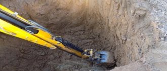
To extract the bulk of the soil from the excavation, various types of excavators equipped with a backhoe or a straight shovel are often used. Work related to digging a pit should be carried out without disturbing the density of the soil at the bottom of the foundation. This requirement is implemented in practice by its shortfall, the value of which ranges from 5 to 20 cm.
Workers clear the earth from the sides and bottom of the excavation to the planned level manually. In this case, you should definitely ensure that its walls are strengthened with the help of slopes, or through the installation of special structures. Precipitation and rising groundwater in spring and summer, exposure to frost in winter - all this contributes to the destruction of the pit.
The soil from the pit must be immediately removed or placed on the construction site no closer than 1 m from its edge. A drainage system is created to drain soil water.
An important point when digging pits is to create a working space of the required dimensions according to the rules. It should occupy at least half a meter from the foundation formwork to the bottom of the slope. The steepness of the pit slopes is selected according to the tables or graphs given in SNiP 3.02.01-87.
Construction properties of soils
The characteristics of soils are determined by the composition, relationship and interaction of the constituents of the rock. Soils can be characterized by physical and mechanical characteristics, magnetic, electrical, water, etc. We are interested in the construction properties of soils, and these are largely physical and mechanical features: relying on them, specialists make all calculations during construction and installation work, choose development technology soil. These soil characteristics determine the physical condition of the soil and the conditions that arise as a result of any impacts on the soil. So, the construction properties of soils:
- density;
- humidity;
- clutch;
- loosening ability;
- angle of repose;
- specific cutting resistance;
- water holding capacity.
Density is the mass of a unit volume of soil, expressed in kg/m3 or t/m3. The density of unconsolidated rocks can reach 2.1 t/m 3, rocky - 3.1 t/m 3.
Humidity is characterized by the ratio of the mass of water in the soil to the mass of dry soil. If the percentage of humidity does not exceed 5%, such soil is called dry, from 5 to 15% - low-moisture, from 15 to 30% - wet, above 30% - wet. The higher the soil moisture, the more difficult it is to develop it. The exception is clay, because On the contrary, it is more difficult to process it in dry form, but with high humidity this process becomes difficult due to stickiness.
Another important property of soils is adhesion. It characterizes the structural connections and how the soil resists shear
The adhesion force of sandy rocks is 0.03-0.05 MPa, and that of clay rocks is 0.05-0.3 MPa. Frozen soils are characterized by significantly greater adhesion.
When rock is mined, it increases in volume; this structural property of soil is called loosening. A distinction is made between initial loosening K p and residual loosening K op (shows how much the soil decreases in volume after compaction). Loosening indicators are given in Table 2. It should be remembered that natural compaction does not proceed uniformly, which can cause subsidence. To avoid such defects, the soil must be compacted using special machines.
According to safety requirements, digging pits and trenches in most cases requires slopes and fastenings. The angle of internal friction, adhesion force and pressure of the soils that lie on top affect the magnitude of the angle of repose. If there is no adhesion force, the limiting angle coincides with the friction angle. The steepness of the slope is determined by the angle of repose a
(provided that the soil is in limiting equilibrium) (Fig. 1).
H/A=l/t, where t is the loading coefficient.
Fig.1. Slope steepness
In table 3 you can see the values of slope steepness for temporary earthworks. When the excavation depth reaches 5 meters or more, the steepness of the slopes is determined by design.
Classification of soils by
specific cutting resistance is presented in ENiR 2-1-1. It is based on the properties of soils and the characteristics of earthmoving and earthmoving equipment that is involved in soil development. There are 6 groups for excavators with one bucket, 2 groups for multi-bucket excavators and scrapers, 3 groups for graders and bulldozers, 7 groups for developing soil without the use of machinery. Soils from the first four groups can be easily processed both manually and using machines, while soils from subsequent groups must first be loosened, sometimes even using an explosive method.
An important property of the soil that affects the tillage process is water-holding capacity (the ability of the soil to retain water in its composition). Clay is characterized by high resistance to water penetration (non-draining soil), while sand is characterized by low resistance (draining soil).
Water holding capacity is characterized by the filtration coefficient K; this value can vary from 1 to 150 m/day.
Sometimes the designer has to draw a pit plan; in fact, this is the simplest drawing - with a minimum of lines and symbols. Now let's look at an example of how to draw a foundation pit.
Pit construction
When choosing a method for performing excavation work, take into account:
- type of construction;
- depth;
- scope of work.
When constructing a strip and columnar shallow foundation, soils can be excavated manually. When building a house with a basement or ground floor, the work must be mechanized.
The main volume of soil is excavated by an excavator with a front or backhoe. In this case, the pit must be torn off without disturbing the density of the soil at the base of the foundation. To comply with this requirement, a shortage of soil is provided within the range of 5-20 cm. Cleaning of slopes and excavation of soil from the base to the design level is carried out manually by general workers.
The selected soil must be immediately removed or placed on the construction site at a distance of more than 1 m from the edge of the pit.
The choice of equipment depends on the type of soil, the depth of the pit and the scope of work. When building a private house with a width of no more than 15 m, you can use a backhoe excavator with a bucket volume of up to 1.4 m3 on a wheeled or tracked chassis.
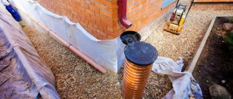
Water reduction techniques
Drainage is needed for the timely removal of melt, ground and rain water. Before carrying out work, a preliminary study of the soil and construction site is carried out, and a suitable method of pumping out water is selected.
The following technical parameters are taken into account:
- the scheme according to which the excavation is carried out;
- volume of water taking into account the capacity of the container;
- hole depth for installing pumps;
- calculation of the amount of water entering the pit;
- determining the time for pumping while maintaining the parameters of lintels and slopes.
Drying technology is a complex set of measures that requires professional participation and the use of equipment. It is necessary to take into account the features and characteristics of the soil and a specific pit.
Standard methods for organizing drainage are used:
- Open drainage. The process is carried out directly from pits and trenches.
- Closed. Pumping is carried out through technological recesses or wells that are located outside the pit. Special filters are used to collect water masses.
In most cases, the open type is used, but the choice depends on the specific conditions at the construction site and the quality of the soil
It is important to follow the requirements of regulations and building codes
During the process of pumping out water, slopes and other reinforcing structures are constantly monitored. If problem areas appear, strengthening is carried out. The quality of work is affected by the condition of the mounting elements and jumpers.
Open
This type of water pumping is becoming the simplest and most common solution. It is suitable in cases where the walls and bottom are made of the following types of soil:
- cohesive, having inclusions of sand and thin layers;
- layered, where soil water flow is at an average level;
- non-cohesive with a dense build, characterized by sufficient resistance to washout;
- waterproof, dense type, in which rain and melt water accumulate.
When choosing an open drainage system, the following designs are used:
Cavaliers This is an embankment of fencing type walls, which is carried out on the upland side or along the perimeter. Upland ditch It is laid if there is a slope on the site. The system is used if water flows into the pit from the top point of the site. Ditches, trays, open drainages Elements allow for effective removal of moisture
It is important to correctly calculate the slope. The requirements of regulations and building codes are taken into account. Pumping equipment Stationary systems or portable compressors are used. The latter elements are used if constant pumping of water is required. Drainage wells The construction of sumps and pits is provided
The system is installed at the bottom of the pit to effectively collect groundwater or melt water.
The latter elements are used if constant pumping of water is required. Drainage wells The construction of sumps and pits is provided. The system is installed at the bottom of the pit to effectively collect groundwater or melt water.
When choosing an open system, detailed calculations are performed. Their use is possible if the slope of the trench is 75-90 degrees. In this case, the minimum slope is 2-3 cm per meter relative to the horizon.
Closed
If the site is characterized by cohesive soils with low resistance to washout, the walls of the pit or trenches may collapse.
In this case, closed systems are preferable. This water treatment option is used for construction on loose soils.
The following techniques are used:
- wellpoint;
- vacuum;
- electroosmosis to expand the range of action of wellpoint units.
The system is based on effectively lowering the water level using artificial means. This is a perfect and effective, but also difficult method to organize. The work is carried out by pumping water through wells that are located along the trench or around the pit.
Steepness of slopes of pits, trenches and other excavations according to standards
The steepness of the slopes of pits, trenches and other excavations is given in the following groups of regulatory documents:
- SP 45.13330.2017 Earthworks, bases and foundations. Updated version of SNiP 3.02.01-87. (mandatory for use from August 1, 2022 according to Decree of the Government of the Russian Federation dated July 4, 2022 N 985)
- Rules for labor protection during construction, reconstruction and repair. Approved by order of the Ministry of Labor of Russia No. 883n dated December 11, 2020 (valid from 01/01/2021)
- Rules for labor protection in construction. Approved by Order of the Ministry of Labor of Russia N 336n dated June 1, 2015 (valid until 01/01/2021)
- SP 45.13330.2012 Earthworks, bases and foundations. Updated version of SNiP 3.02.01-87. (valid and mandatory until August 1, 2022 for use in accordance with Decree of the Government of the Russian Federation dated December 26, 2014 N 1521
- SNiP 12-04-2002 “Labor safety in construction. Part 2. Construction production" (advisory)
Let us highlight the requirements given in these documents, which directly relate to the magnitude of the steepness of the slopes.
Types and features of walls and slopes of trenches, rules for calculating their angle
Digging and using trenches is a mandatory measure during construction and road work of varying complexity.
Despite the fact that the work seems to be simply a mechanical activity, it has a number of features that must be observed to achieve the desired result.
How to make the walls and slopes of a trench stable, what types of them there are, how to organize the work correctly, we’ll figure it out in the article.
What are the requirements for excavation work?
Reliability and stability of earth structures is the main requirement. In order to ensure its implementation, it is important not only to dig a recess, but also to plan slopes, the steepness of which must meet the stated standards. This characteristic mainly depends on the natural angle of repose of the soil at the construction site.
The steepest slopes can be those of trenches whose depth does not exceed 5 meters, located on non-rocky soils that are above sea level, or those that have been artificially drained, as recommended by SNiP.
Trench slopes are sloping side walls of depressions in the ground that can crumble or deform. That is why it is so important to follow all norms and recommendations.
The steepness of the slopes is the ratio of the height of the embankment slope to its base. It is by calculating the correct steepness that you can be sure that the slope will not slide and that the embankment will be stable and safe.
When choosing a method for creating walls and slopes, experts are guided by a number of characteristics that
can significantly affect the main decision:
- Terrain.
- Climatic conditions.
- Hydrogeological characteristics of the area where the trench will be. This point is especially important, because if floods may occur in the area where the work is being carried out, then standard methods will not work.
Only all this data taken together can provide an understanding of the full picture.
- If the trench is dug in the ground, with a normal level of humidity, vertical walls and without additional fastenings, then the depth standards look like this:
- in bulk and sandy soils, the depth cannot be more than 1 meter;
- in sandy and loamy soils - do not exceed 1.25 meters;
- if the ground is clayey, then the limit is set at one and a half meters;
- if the soil is particularly dense, then the trench can be up to 2 meters deep, but on the condition that all other work will be carried out immediately.
- If development is carried out on frozen soils of any type, the trench can be to the full depth of their freezing. The only exception is dry sandy soil, which, due to its mobility and friability, does not have the necessary characteristics. If you need to go even lower, but special supports are needed for the walls.
- Digging a trench in soils that were previously exposed to frost, but then returned to their natural state, has its own characteristics. It is important to maintain the steepness of the slopes, or equip additional support for the walls.
Only if the standards are followed can you be sure that the structure will be stable and reliable.
Varieties
Even at the stage of planning the trench and drawing up a figurative drawing, the designer must decide what walls and slopes he will have. Each individual variety has its own characteristics:
SP and SNiP requirements
The principles and requirements for calculations are set out in construction regulations (SP - codes of rules and SNIP - building codes and regulations, TTK - standard technological maps).
Construction rules and standards for excavation work when constructing trenches are approved in:
- SP 45.13330.2012 on earthen structures, which sets out the basic requirements for the arrangement of trench widths, wall heights, and permissible deviations;
- SP 104-34-96 on excavation work;
- SNiP 2.05.06-85 on underground laying of pipelines;
- SNiP III-42-80 on earthworks.
Requirements may differ for gas pipelines, water mains and other process facilities.
Design engineer website
- > Home
- > Calculations
- > Load-bearing structures
- > Insulation materials
- > Drawings in dwg format
- > Projects repeat. applications
- > Directory of materials
- > Hardware
- > Buildings and structures
- > RAL, textures, colors
- > Design software
Recent Entries
Data and Formulas
Before making calculations using formulas, it is necessary to determine the site features and pipeline characteristics that affect the parameters used.
The amount of corrections to determine the total volume of soil and the permissible steepness of slopes depends on the quality of the soil. Different percentages are used when working in sandy soils, light and heavy loams, soft or oily clay, taking into account crushed stone admixtures.
The location of the work must be taken into account. Laying trenches in a field, on a city street or in a residential yard determines the characteristics of the equipment used and the permissible minimum depth.
First, the required trench depth (H) is calculated. It depends on the level of the permissible minimum depth (Nmin) and the diameter of the pipeline (pipe diameter + insulation thickness - Ø with insulation): N = Nmin + Ø with insulation.
The next indicator is the width of the trench (B), which is determined based on the diameter of the pipes and tolerances. The amount of tolerance around the pipe depends on the nature of the installation (individual pipes, sections, strands). The total width cannot be less than 0.7 m, and in the presence of side fastenings - 0.8 m: B = Ø with insulation + tolerance.
The width of the trench along the bottom and top is equal only in dense soils; on sandy and sandy loam soils the trench will have the shape of a trapezoid. In these cases, it is necessary to calculate the steepness of the slopes, taking into account the depth and length of the trench.
The steepness of the slope (Kot) or slope is defined as the ratio of the depth of the excavation (H) and the foundation, for example:
- Cat = N/V = 1: 1 at a slope of 45°;
- Cat =H/V = 1: 0.5 at a slope of 63°;
- Cat = N/V = 1: 1.25 at a slope of 38°.
The resulting coefficient allows you to determine the width of the trench in its upper part; for this, double the size of the slope is added to the base parameters.
The volume of work (V) for excavation is calculated separately for manual and mechanized development. Based on practical experience, the ratio (Kr) is 95 and 5%% outside the populated area and 85 and 15%% inside the city.
To determine the average width (S), you need to add the lower and upper dimensions, fold them and divide them in half: W= (A+B) : 2.
The volume of soil excavated mechanically is equal to: Vex. = W x N x L x (Krm/100) (m3), where Krm = 85 or 95.
The volume of soil removed manually is equal to: Vman. = W x N x L x (Krm/100) (m3), where Krm = 5 or 15.
The total volume of pits is usually up to 5% of the total size of the entire trench.
Taking this into account, the total volume of work at the first stage is determined, which is equal to: Vtotal development. = Vex. + V.hand. + 0.05 (Vex. + V.hand) (m3).
The second part of the excavation begins when filling the trench. This procedure consists of several sequential steps. First, the pipes are backfilled by hand. The height is equal to the diameter of the pipe, taking into account insulation and backfilling of at least 20 cm on top: h = Ø + 0.2 (m).
To determine the total backfill volumes, you need to find the volume of the trench that is directly occupied by the pipeline. To do this, we use the formula for the area of a circle and the length of the trench: V pipe = π Ø /4 x L (m3).
For further calculations, you need to subtract the calculated dimensions of the pipe from the total volume of excavated soil and add the dimensions of the embankment above the soil surface, if there is one.
In another way, the volume of backfill is calculated as the sum of work performed manually and with a bulldozer:
- The share of manual work is V manual. zas. = A x h x L - V pipes (m3).
- Share of bulldozer work: V mech.zas. = (A+B)/2 x (H – h) * L (m3).
Additionally, the volume of previously dug pits is added minus the size of the equipment installed in them.
To check, you can calculate the balance of the earth mass: V general development = V manual filling + V laid pipe + V mechanized filling.
To determine the volume of soil that needs to be removed, you need to take into account the amount of soil that will not return to the trench. For this purpose, the already known data of the excavated soil and the residual loosening coefficient (Ko) are used. This adjustment is necessary because there is a difference in volume between the dense soil removed and the loose soil returned.
The residual indicator is calculated as a percentage and is taken in the methodological recommendations: V residual = V total development x (Ko/100) (m 3).
The remaining soil will be scattered throughout the surrounding area if construction is taking place in an open field. In the city or other cramped conditions, excavated and unreturned soil must be removed.
Before ordering vehicles for removal, you need to know the volume of soil that needs to be loaded into the vehicles and removed. For this, the formula is used: V removal = V pipes + V residue (m3). Based on the volume, the number of dump trucks is selected taking into account their carrying capacity.
Additional calculations may be necessary, for example, to install a fence you need to know the perimeter of the trench. To do this, add the length and width (top), and then multiply them twice: P = (L + B) x 2 (m).
If the trench has a complex shape, then calculations are made for each section, and the results are summarized.
Example calculations for a trench with the following data:
- length L = 100 m;
- bottom width A – 1 m;
- top width B -1.5 meters;
- pipe diameter with insulation Ø – 0.7 m;
- laying depth – 1 meter.
Let's calculate the volume of soil excavated mechanically and manually, as well as the total amount, taking into account the pits:
- Vex. = (1+1.5)/2 x 1 x 100 x (95/100) = 118.75 (m3), where Krm = 95%;
- Vhand. = (1+1.5)/2 x 1 x 100 x (5/100) = 6.25 (m3), where Krm = 5%.
- Vtotal = Vex + Vhand + 0.05 (Vex + Vhand) = 118.75 + 6.25 + 0.05 (118.75 + 6.25) = 131.25 (m3).
Similarly, further calculations can be made at the stage of backfilling the trench.
Determining the scope of work on site slopes
For corner slopes, the volume of earth masses is equal to
where m is the steepness of the slopes for excavation: h up to 1.5 m m = 0.25
for excavation: h up to 3m m=1
h—working elevation of the site corner, m
For ordinary slopes
where the side of the square is a=50 m
h1,h2-working marks of adjacent vertices of squares located along the perimeter of the site, m
For ordinary slopes with one zero working mark
where a1 is the part of the side of the square from the working mark to the zero point, m.
Table 2.1 Determination of slope volumes
| Figure No. | Side of a square | Slope steepness | Working marks H1 H2 | Volume volume, m 3 | Embankment volume, m 3 |
| 24,87 | 0,25 | -0,96 | — | 5,73 | |
| — | 0,25 | -0,96 | — | 0,0184 | |
| -0,96 | -1,86 | 44,17 | |||
| 1,25 | -1,86 | -3,13 | 207,13 | ||
| 1,25 | -3,13 | -4,44 | 461,1 | ||
| 1,25 | -4,44 | -4,2 | 583,65 | ||
| — | 1,25 | -4,2 | — | 38,58 | |
| 1,25 | -4,2 | -3,41 | 457,31 | ||
| 1,25 | -3,41 | -2,23 | 259,39 | ||
| -2,23 | -0,6 | 266,645 | |||
| 26,56 | 1,5 | 0,68 | — | 18,42 | |
| — | 1,5 | 0,68 | — | 0,235 | |
| 1,5 | 0,68 | 0,84 | 21,9 | ||
| 1,5 | 0,84 | 1,87 | 78,79 | ||
| 1,5 | 1,87 | 2,89 | 222,17 | ||
| 1,5 | 2,89 | 3,85 | 434,52 | ||
| — | 1,5 | 3,85 | — | 42,79 | |
| 1,5 | 3,85 | 3,21 | 471,12 | ||
| 1,5 | 3,21 | 2,41 | 194,65 | ||
| 1,5 | 2,41 | 0,97 | 126,54 | ||
| 25,13 | 1,5 | 0,97 | — | 35,47 | |
| 23,44 | 0,25 | -0,6 | — | 2,11 |
Table 2.2 Adjusted list of volumes (including slopes)
| Plot number | Excavation volume, m 3 | Embankment volume, m3 |
| 8335,93 | ||
| 4984,67 | ||
| 2484,04 | ||
| 713,975 | ||
| 95,89 | ||
| 5575,9 | ||
| 1936,01 | ||
| 38,11 | ||
| 295,83 | ||
| 796,79 | ||
| 0,93 | ||
| 1537,465 | ||
| 3139,04 | ||
| 431,37 | ||
| 576,02 | ||
| 6953,14 | ||
| 297,22 | ||
| 1240,3 | ||
| 3,53 | ||
| 3384,46 | ||
| 8104,85 | ||
| 10617,04 | ||
| total | 37619,065 | 28198,445 |
2.3Distribution of volumes of earth masses during vertical planning
Where to get constant values?
There are a number of mandatory requirements for excavation work that are taken into account when designing construction.
All main parameters are given in industry SNiPs and SPs. They are designed taking into account construction safety requirements.
For example, SP 45.13330.2012 on earthworks provides a table of the minimum width of trenches, calculated based on the method of soil development and the method of connecting pipes:
| Pipeline laying method | Welded Width | Width for coupling, flange connection |
In separate sections if the outer diameter of the pipes:
|
| |
| Also with the narrow trench method (Ø up to 219 mm) without lowering people into the trenches | ||
Individual pipes with diameter:
|
|
|
Here is a table of the minimum dimensions of pits, taking into account the type of pipes, method of connections, sealant, and nominal diameter of the pipeline.
Topographic designation of the well on the site plan
The designation of a well on a site plan and on topographic maps is of great importance, especially in desert and semi-desert areas. Like other hydrographic objects, they are indicated in blue in the form of circles with a nearby letter K or the signature “art.k.” (artesian well). All designations on maps and plans are called conventional cartographic signs. To make them convenient to read and easy to remember, many signs have a visual similarity (side or top view) with the designated object.
Classification of conventional signs
On maps and plans, all terrain elements are indicated by symbols. They are usually divided into 3 independent groups:
- scale or outline;
- off-scale;
- explanatory.
In order to make the depicted signs more visual, all elements of the same type are painted with the same paint, i.e., any hydrographic element is indicated in blue.
Objects of the same type on maps with different scales are indicated the same way and differ only in size. The larger the scale of the map, the more objects can be plotted and information indicated on it. Small structures of secondary importance, as a rule, are not depicted on them, thereby increasing the clarity of the image.
How is the compaction factor calculated?
This requires laboratory or, for private housing construction, home tests.
A sample of material is compacted to the extent that will be organized on the construction site, after which measurements of the compacted sample are compared with measurements before compaction.
The general principles of testing, the equipment and methods used are described in GOST 22733-2016 and GOST 8269.0-97.
For a more complete understanding of the process of checking the degree of compaction of bulk materials, we recommend watching the video.
You can also use more accurate soil density meters.
ASG compaction coefficient
Sand-gravel mixture (SGS) is a natural or enriched (OPGS) mixture of sand and gravel. The composition of the natural mixture is standardized by GOST 23735-2014; according to GOST, the content of gravel grains with a fraction of about 5 mm should be within 10...90%.
This material is rarely used for filling a sand and gravel cushion under the foundation; it is more often used for the production of medium and heavy concrete. Accordingly, the grain size and percentage composition of the mixture greatly influence the compaction coefficient of concrete.
The ASG group must be taken into account according to the table.
What is transportation compaction factor
This name refers to the ratio of the volume of material at the time of loading the vehicle to the volume at the time of delivery.
Taking into account the fact that during transportation bulk material is inevitably compacted - road shaking plays the role of compaction - the minimum acceptable coefficient for accepting crushed stone, sand or sand-gravel mixture delivered to the site is considered to be 1.1. That is, data on the volume of the body (car, other transport capacity), multiplied by a factor of 1.1, must match the ordered volume or slightly exceed it. If the resulting figure is less than the required one by 2...5% or more, it is necessary to resolve the issue of shortage of material.
Example.
20 cubic meters of crushed stone were ordered, 18 cubic meters were delivered. (according to measurements from the inside of the body). Taking into account the coefficient 18x1.1=19.8 cubic meters. The underload is 0.2 cubic meters, that is, 1% - the error is within the permissible limit.
Important: data on the compaction of the material during transportation may be indicated, but is not required to be indicated in the accompanying documents of the cargo! To avoid misunderstandings, ask the supplier to include the data in the sales and transportation agreement.
Concept
The walls of the pit are its sides, forming the perimeter of the excavation. Slopes are walls inclined at a given angle. Depending on the type of soil and the conditions in which the work is carried out, it is determined whether the walls of the pit should be vertical or whether a certain slope must be specified.
The slope allows you to dig deeper holes without the risk of collapse. During the work, large stones should be removed to prevent the possibility of landslides.
Methods of excavation work, mechanisms used
Depending on the soil, different equipment is used in the construction of trenches and pits, and various methods are used to develop construction sites. They differ in labor intensity and the level of required material costs. According to SNiP 111-4-80, the following methods are identified:
- hydromechanical;
- mechanical;
- carrying out blasting operations.
The mechanical method of developing pits and trenches is the main one. Its essence lies in digging soil using earth-moving (excavator) machines, or earth-moving and transport machines (scrapers, bulldozers, graders).
The hydromechanical method is based on eroding the soil mass with a jet of water from a hydraulic monitor. Then the resulting solution is sucked into the dredge.
Blasting works are used mainly in suburban construction. First, holes (wells) are drilled in the ground. Then they put explosives in them and detonate them. The resulting loose mass is removed using machinery.
Mechanical method of digging holes
The mechanical method consists of a number of stages:
- loosening the soil;
- development of rock mass;
- its transportation;
- leveling, compacting side slopes and bottom.
Work on creating recesses using a hydromechanical method takes place in the following sequence:
- designate the work site area using fences, inscriptions, and warning signs;
- according to the standards, a hydraulic monitor is installed, manually controlled by the operator: the distance from its nozzle to the wall of the pit must be no less than the height of the excavation, and to the nearest overhead power line - at least two intervals over which a stream of water can be supplied by this equipment;
- Slurry pipelines and water conduits are placed behind the security perimeter of power lines;
- protect the dumping areas of the reclaimed earth mass;
- produce erosion and excavation.
It is prohibited to operate the hydraulic monitor during a thunderstorm.
Conducting blasting operations is regulated by relevant rules.
When mechanical loosening of the earth mass is carried out using the impact method, then workers should not be within a radius of 5 m from the site of loosening.
Any equipment must be located during operation in accordance with current standards and rules. Deviation from them often causes accidents.
Safety measures when digging pits
The soil from the side walls of a pit or trench, as a result of the action of gravity on them, can move and fill the bottom of the excavation. Due to the uncontrolled collapse of earth masses, accidents to people are possible. Also, destruction leads to an increase in labor costs and money: it will be necessary to restore the planned contour of the excavation and backfill the foundation with a large volume of soil.
In order to prevent crumbling and reduce the possibility of material losses to a minimum, it is necessary to correctly calculate, at the design stage, in accordance with SNiP 111-4-80, the steepness of the slopes of the excavation being created.
If the depth of a trench or pit, on average, exceeds 1.25 meters, then it is necessary to strengthen their walls in order to prevent possible collapses and earth slides. Along the contour of the excavated structures, strips should remain free from the excavated soil mass, the minimum width of which is more than 0.6 m. The earth from the excavation should not roll back.
The parameters of the side slopes must be determined correctly before developing the pit. This will allow:
- prevent the possibility of collapses;
- perform the optimal amount of excavation work;
- will eliminate the cost of altering slopes during construction work.
Landslide prevention is a major safety concern for personnel.
Compliance of slopes with optimal angles of inclination for a given type of soil minimizes monetary and labor costs for backfilling and rework.
Slope formation
Before starting work, geological and hydrological surveys of the building site are carried out. If there is soil water, unstable soil, or if it is necessary to dig a hole more than 5 m deep, a project is created for the identified individual conditions.
According to SNiP 111-4-80, for non-moist soils with a uniform structure, vertical side walls can be left when digging trenches or pits. In this case, there should be no structures near the excavations and no groundwater. The permissible depth of excavations for different soils with vertical walls is for:
- gravel, sand – 1 m;
- sandy loam – 1.25 m;
- clayey and loamy - no more than 1.5 m;
- very dense - 2 m.
In pits with a depth of about 1.25 m, it is required to use stepladders that will rise above the ground to a height of at least 1 m. In deeper excavations, flights of stairs are used.
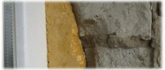
The side surfaces of the pits may be strengthened with construction. If there is a possibility of additional loads or slopes being washed out, they are covered with film or shotcrete is carried out (concreting with a thin layer).
Soil stabilization technologies
Depending on the geological characteristics of the construction site and the climatic characteristics of the area, the depth of the excavation, and the characteristics of the structure being constructed or reconstructed, various methods of soil consolidation are used in practice. Technologies can improve their resistance to destruction. SNiP111-4-80 identifies the following fastening methods:
- thermal;
- cement;
- using cement mortar.
Various types of mechanical fastenings are often used. Based on their design, the following types are distinguished:
- braced;
- cantilever-spacer;
- spacer;
- cantilever-anchor;
- console
The choice of fastening type is made based on the above factors that influence the correct execution of the work.
According to their design and the possibility of quick installation and dismantling, the following types of fasteners are distinguished:
- stationary;
- inventory;
- with intervals;
- solid.
Securing the Excavation Walls
The upper part of the fasteners after their installation should rise above the edge of the pit or trench by more than 0.15 m. In this case, the installation itself is carried out from top to bottom during the excavation of earth masses, and disassembly is carried out in the opposite direction when backfilling.
The spacer type of fastenings is most widespread. This option is used if the trench depth does not exceed 3 m. The structure consists of the following elements:
- shields;
- screw spacers or frames;
- racks
The side surfaces of the trenches are secured immediately after their excavation.
On weak, wet soils, cantilever-spacer or cantilever types of fastenings are used. The depth of the excavations should be within 3 m.
A type of cantilever-type fastenings are tongue-and-groove fastenings. They secure the walls of deep pits, where there is high pressure from the sides and difficult hydrogeological conditions.
Strut fences are rarely used because they make work difficult.
The method of fastening is determined by the design documentation. If these measures are necessary during individual development, you can rent various fasteners, or make metal or wooden analogues of factory-made products yourself. Determining the choice in favor of one or another fastening option depends on the conditions at the construction site.
The videos below show various methods of securing the soil on the slopes of a pit.
The process of forming a slope with an excavator is demonstrated in the following videos.
Giving stability to the side surfaces of pits is the first requirement that is presented when creating them. In order to ensure safe working conditions, prevent landslides and comply with construction technology, excavations with slopes of the required steepness are erected.
If the depth of the pit does not exceed 1 m, then on any type of soil there is no slope on the side surfaces, and for hard rocks, vertical walls of the excavation are left even at depths of up to 2 m. The slopes of the pits are formed according to SNiP tables if the depth is up to 5 m. After exceeding this value - perform special calculations.
Soil: groups and types
Due to the fact that earthworks are created in soils, you should definitely know their basic characteristics. The appropriate type of foundation directly depends on them. The choice is made taking into account achieving the highest possible level of reliability and durability of the foundation being built.
The main properties of the soil are determined by the following factors:
- shape, size, strength, arrangement of particles included in its composition;
- the degree of relationship between them;
- the ability of constituent substances to solubilize and absorb moisture.
Soil is characterized using the following coefficients:
- compressibility;
- friction;
- plasticity;
- loosening.
The classification involves dividing soils according to various criteria. There are the following types:
- sandy;
- dusty;
- clayey;
- rocky;
- clastic.
Different types of soil Depending on the water content, soil is distinguished:
- dry (up to 5% moisture present);
- wet (5-30%);
- wet (contains more than 30% water).
The division into groups is presented in the table below.
| Category | Included soil varieties |
| 1 | sandy loam, sand, light loam (wet), peat, plant layer soil |
| 2 | light damp clay, fine to medium gravel, loam |
| 3 | dense loam, medium and heavy (loose) clay |
| 4 | frozen soils (clayey, loamy, peat, sandy, sandy loam, plant layer), heavy clay |
| 5 | fragile limestone and sandstone, strong clayey shale, permafrost (with admixtures of crushed stone, pebbles, boulders, gravel up to 10%), moraine and river (with large boulders and pebbles content up to 30%) |
| 6 | strong shales, clayey sandstone, marly limestone, fragile serpentine and dolomite, fluvial and moraine (inclusions of boulders and pebbles - up to 50%), permafrost (with a share of gravel, boulders, pebbles, crushed stone - up to 20%) |
| 7 | hard limestone and sandstone, dolomite, serpentine, mica and silicified schists, marble, permafrost (stone components account for up to 70% of the volume) |
Soils are also divided into the following types:
- quicksand;
- soft;
- average;
- strong.
Standard data for slope design
The construction of a pit with vertical walls without fastening is allowed only when developing:
- bulk, sandy or gravelly soils to a depth of no more than 1 m;
- sandy loam and loamy - no more than 1.25 m;
- clayey – by 1.5 m;
- especially dense - 2 m.
If a pit of greater depth is required, it is necessary to take the steepness of the slopes recommended by SNiP, taking into account the type of soil and the depth of the foundation. Moreover, if the depth of the pit or trench exceeds 5 m, then a calculation is performed to determine the stability of the earth masses.
Fastening the walls of a pit with a depth of 2-3 m must be carried out strictly according to the standard design.
In the regulatory literature, the steepness of pit and trench slopes is measured as the angle of slope (ɑ) or the ratio of slope height to foundation (1:m). In SNiP, these data are presented in tabular form separately for each type of soil, taking into account the excavation depth.
If there are several types of soil on the site, then the steepness of the slopes is taken based on the most unstable layers.
Due to the fact that even when developing a pit with slopes, the possibility of soil collapse under the weight of machinery cannot be excluded, it is necessary to observe the distance required in SNiP from the bottom of the slope to the location of the equipment.
When calculating the volume of excavation work, take into account the size of the slopes, which increase the width of the pit by b=m*h.
How is it carried out?
After the soil has been excavated, the pit needs to be strengthened; for this purpose, horizontal, vertical elements and structures with a wooden fence are used.
Horizontal fastening consists of elements:
- wood;
- reinforced concrete;
- metal
Horizontal strengthening of the walls is used when marking the bottom of the pit above the groundwater level.
This method has also shown itself to be effective in the construction of small and complex objects, when the height of the loose part of the wall does not exceed 50 cm. The walls are strengthened horizontally when they are separated from each other by a small distance.
Dismantling of horizontal fastenings occurs during construction work
There is an important condition here - the work is carried out slowly and carefully. Since such fasteners support vertical walls like struts, when removing one of the structural elements, there is a risk of collapse of the entire system
Due to the large number of cross braces, there are restrictions on machine insertion and there is also the possibility of the walls becoming unstable when the struts are removed.
The work happens in this order:
- The through boards that act as spacers are sawn through. They need to be sawed into 2-3 pieces.
- Temporary spacers are prepared and installed.
- The fastenings are disassembled.
- Structural elements are fed to the surface above the pit.
Materials used
For different types of foundations, it can use both local compacted soil and imported materials. Most often, local semi-rocky and sandy soils are subjected to compaction. Already loams, and even more so clayey soils, must be removed to the depth of the pit and replaced with a cushion of sand and gravel.
In this case, the base layers must be subjected to compaction, the effectiveness of which depends on the following factors:
- layer material. For crushed stone of different types, gravel, gravel-sand mixture (GSM) and sand, the compaction coefficient is very different;
- fractions of material. The larger the fragments, the more difficult it is to compact them;
- tamping method - manual, mechanized - and the force applied;
- height and total volume of the backfilled layer;
- the presence of material with a grain size less than that specified by the lower limit of this class (for example, for crushed stone of fraction 5...20, the content of stone up to 3 mm in size inclusive is about 5% - such a discrepancy will have little effect on the degree of compaction. If the percentage is ¼...1/4 volume – adjustments will have to be made);
- flakiness (for crushed stone). This parameter expresses the ratio of the content of cuboidal stones to flat ones. The lower the flakiness, the more cubic elements and the more densely the crushed stone can be compacted;
- layer moisture.
Engineering-geological surveys
Strip monolithic foundation
These studies are necessary to ensure that the house remains strong and durable for many years. There may be landslides where your home is being built. When building a house, the depth of the foundation must be observed. SNiP regulates this indicator.
Construction work on hillsides is not recommended. And if you decide to take this step, then you need to approach this issue carefully and comprehensively. Most often, experts recommend strengthening the soil, making a strong foundation and piles.
If quicksand is found at the site of your future house, then it is possible that in the near future cracks will form in your house and the foundation may collapse.
When constructing a country house, one should take into account frost heaving in loams and clays, the presence of deformable peat soils, heterogeneity of the foundation, the possibility of landslides, the general rise of groundwater, seasonal temperature fluctuations and much more.
If the base of the foundation is located above the freezing depth, then on clay soils due to frost heaving, deformation of door and window openings is possible. As a result, the building requires expensive repairs.
If the soil under the base of the foundation is heterogeneous, then different parts of the foundation go into the ground to different depths. As a result, cracks appear on the walls. Therefore, before construction begins, geotechnical surveys must be carried out on the site.