Every homeowner is familiar with the consequences of heavy rainfall and spring snow melt.
And if, at the stage of constructing a private house, you do not take care of the construction of a storm drain on the site, then all this can result in serious problems.
Such measures will help prevent the formation of a swamp in the yard, flooding of the basement and foundation, and at the same time, it will protect the walls of the house from destruction from the outside.
Storm drainage in the house
Norms
Inside the apartment there is practically no way to measure the fluid flows in the sewer system using your own capabilities.
Professionals advise to be sure to take into account the permissible numbers indicated in the regulatory tables. According to SNiP recommendations, the flow speed should be 0.7-1 m/sec. For such a speed, the standard angle of inclination should be for products with a diameter of:
- 5 cm – 30 mm per linear meter;
- 11 cm – 20 mm per linear meter;
- 16 cm – 8 mm per linear meter;
- 20 cm – 7 mm per linear meter.
The regulatory documents that specify these rules are:
- Clause 18 SNiP 2.04.01/85. The structure of internal drainage and sewage systems for buildings is described in detail here. For example, from here you can find out that drainage branches with a cross-section of 4-5 cm should be laid with a slope of 0.03, and with a cross-section of 8.5-10 cm - 0.02.
- Clause 2.41 of SNiP 2.04.03/85 on external sewage drains describes the rules regarding the minimum slope of pipes measuring 15 cm. It should be equal to 0.008 cm, and for pipes measuring 20 cm - 0.007 cm.
- If there is a need to make the network slope smaller, you can be guided by clause 18.2 of SNiP 2.04.01-85. This point takes into account the peculiarities of liquid flow through pipes with different physical characteristics. For example, for plastic pipes the speed coefficient should be 0.5, and for networks made of other materials the coefficient should be 0.6.
A separate explanation in SNiP 2.04.03/85 concerns external sewers with pipe sizes of 15-20 cm. In particular, the rules allow the use of standard indicators for slopes: 0.005 for 20 cm products, 0.007 for 15 cm products.
Clause 18 of SNiP 2.04.01/85 regulates the maximum slope of networks, which should not be more than 0.15. At the same time, branches from plumbing fixtures, the length of which is up to 150 cm, are excluded from the calculations. Thus, on each meter of the sewerage system no more than 15 cm of slope is allowed. If the indicator is exceeded, the highway will silt.
Special tables can help with calculations.
| Plumbing device | Diameter, cm | Slope per meter, cm | Gap between central drain and siphon, m |
| bathroom | 0,4 | 3 | 1-1.3 |
| bath, shower, washing machine | 0,5 | 4.8 | 1.7-2.3 |
| shower room | 0,4 | 4.8 | 1.5-1.7 |
| toilet | 10 | 2 | Until 6 |
| bidet | 0,3, 0,4 | 2 | 0.7-1 |
| washing | 0,3, 0,4 | 3.6 | 1.3-1.5 |
| sink | 0,4 | 1.2 | 0-0.8 |
| main riser | 10 | ||
| branches from the riser | 6,5-7,5 |
In the mathematical system, angles are measured in degrees, so the numbers given in tables often become unclear. And the numbers mean the fractional ratio of the height of the slope to the length of the drainage system. It will be easier to track the value if you convert the numbers to centimeters. For example, 3 cm by 1 meter, 0.8 cm by 1 meter. If the length of the entire sewer is known, you can multiply it by the slope, which will give the total height for the entire designed sewer.
Slope of trays why and how
Stormwater inlet trays are gravity-flow systems that, for proper functioning, need to create a constant, uniform slope towards the inlet collector. The entire range of characteristics of storm and domestic sewage systems is described in SNIP 2.04.03-85. This document regulates materials, technical requirements, as well as methods of hydraulic calculation and calculation of wastewater volumes. Of course, the main reference when determining the volume of rainwater is to the region, the intensity of precipitation in it, as well as the coverage around the storm channel. The minimum slope of the tray depends on this, which is 3 millimeters per meter of highway.
However, this value is minimal and depends on the coverage around the trays, as well as on the catchment area. The higher the area and the worse the surface absorbs water, the higher the hydraulic cross-section and slope of the system. Do not forget that water drained from the roofs of houses is often discharged here, into the storm drain. Therefore, in this case, the system must have high throughput.
The creation of storm drainage systems largely involves a large amount of excavation work. To minimize excavation work, the industry produces a tray with an internal slope, which greatly simplifies the installation of the entire system. These products already have the required slope. At the same time, the tray itself remains its characteristic shape, and only the inner gutter is subject to slope. In addition, the use of such water conduits significantly reduces the risks of errors and subsequent malfunction of the storm sewer. Such trays are often made of plastic, since it is quite easy to control its shape during production. However, a concrete tray with a slope, which is also produced, is no exception in this series. Such gutters are created by vibration compaction, which allows achieving high geometric accuracy, including the minimum required slope.
Much, when determining the required slope of the system, depends on the roughness of the inner surface of the tray. The lower it is, the less resistance the flowing water flow experiences, which means the higher its speed and the throughput of the entire system. The leader here, of course, are plastic trays, which have minimal surface roughness. This means that the slope of storm gutters made from such gutters can be made smaller.
However, we should not forget that any storm drainage system is not only gutters. Also a mandatory element of the system are sand traps, which work as small settling tanks in which a suspension of large fractions settles. To minimize the frequency of cleaning sand traps, the trays are often equipped with grates that protect the entire system from large debris.
Features of the depth of storm drainage according to SNiP
The regulatory document does not provide precise instructions on the depth of pipes. But there are some recommendations. When choosing depth, several important factors are taken into account
They take into account the depth of soil freezing, the occurrence of water, and the personal experience of the specialist.
Recommendations for choosing the depth of storm drains:
- If the dimensions of the pipes are less than 500 mm, then they should be laid 30 cm below the soil freezing level;
- If the diameter exceeds 500 mm, this figure is 50 cm.
The thickness of the sand cushion should be added to the burial depth. This is the indicator that is considered optimal. In any case, there should be at least 70 cm from the surface of the earth to the pipe. But if installation to the required depth is not possible, then you will have to make additional insulation and provide protection from mechanical damage.
What should you follow when determining the slope?
If we take into account all the SNiP rules for organizing the inclination of sewer pipes, the general list will look like this:
- The maximum possible slope is 15 cm.
- When installing an external sewerage system, it is necessary to take into account the factor of soil freezing depth.
- When determining the slope of structures, it is recommended to seek the help of specialists and additionally check the calculations using regulatory literature. (possibly on your own)
- When installing a sewer system in a bathroom, you can resort to a minimum slope, since there is no risk of clogging the pipe with large particles.
- You can determine the slope using a bubble level. It needs to be laid in the place where the pipe is located, and depending on the position of the bubble, calculate the amount of inclination.
Also, before carrying out work, it is necessary to draw up a plan for the sequence of actions to avoid possible mistakes. The sewerage profile is also applied to the plan, and this item is prescribed by GOST 21.604-82.
If you take into account all the requirements of the documents, you will be able to organize a sewer system and ensure a normal slope with your own hands.
Important features of laying sewer pipes
- When installing a pipeline system in deep basements or in places with low relief, versions with an extremely low sewer installation depth are provided, in which the installation of a pumping station is provided. The depth of the pressure line must be calculated according to the requirements of regulatory documents.
- Practice has shown that in problem soils (water-saturated, compacted to strong and silty) communications should be laid to a depth of four meters, in dry soils the depth is determined from four to seven meters.
- Communications built with a depth of less than 0.7 meters must necessarily have a sewerage protection zone on the surface of the earth. The security zone is equipped with a system to protect against possible mechanical damage to the pipeline.
- When carrying out projects for laying sewer communications, it is mandatory to take into account the difference in terrain relief lines.
Organization of slope in a private house
The volume of wastewater in a country house is significantly less than in an apartment building. Under these conditions, even with a minimum slope determined from a hydraulic calculation table or formula, the filling level will be insufficient for self-cleaning of the pipe.
It is impossible to reduce the slope even more, since the flow rate will become too slow. Sand with other solid inclusions will settle to the bottom, and the pipe will probably clog. In such a situation, the required angle of inclination of the pipeline is determined by a non-calculation method.
Non-calculation method for determining slope
According to regulatory documents, the non-calculation method is used in cases where, due to the small volume of wastewater, it is impossible to fulfill the condition for the relationship between the optimal and actual filling level.
The old version of SNiP 2.04.01-85 set out the following recommendations on slope for undesigned sections of gravity pipelines:
- Pipe diameter 40 or 50 mm – 0.03
- Pipe diameter 85 or 100 mm – 0.02
The updated version of this SNiP, set out in SP 30.13330.2016, suggests that the minimum slope value for non-calculated sections of the pipeline should be considered equal to 1/d, where d is the outer diameter of the pipe in mm.
Recommendations from specialists for laying a collector from an individual country house to a septic tank:
- A medium-sized house with two bathrooms - 110 mm pipe with a slope of 0.02
- House with three or more bathrooms - 160 mm pipe with a slope of 0.08
Compliance with the proposed parameters preserves the transporting capacity of the liquid flow in the pipeline.
Slope check
The best device for checking the angle of inclination is a level. The device measures the depth of the trench under the pipeline at control points, and the difference is compared with the required value. If there is a deviation from the calculated value, the trench depth is adjusted.
To check the slope without a level, use a simple method using available tools. Two pins are inserted into the bottom of the trench at both ends. The cable is pulled between the pins and the horizontal position is checked using a building level. If necessary, leveling is done.
Then, near both pins, measure the height from the bottom to the cable. After determining the magnitude of the difference, proceed in the same way as in the situation with a level.
In the figure below, the initial depth of the trench is 0.5 m. Based on the recommended slope of 0.02 for a 110 mm pipe, we obtain:
We add the calculated depth difference of 0.6 m to the initial depth of 0.5 m and obtain a trench depth at the end point of the pipeline of 1.1 m.
Solving the problem of a steep slope
If in the direction of laying communications the steepness of the slope exceeds the standard slope, then at some point the more gently located pipeline will come to the surface. The problem can be solved in two ways.
The first option is to make vertical decreasing sections in the pipeline as it approaches the surface. In the second option, a large vertical depression is immediately made, which is enough for the entire length of the collector.
Downgrade scheme according to the first and second options
How to choose the angle of inclination?
In the process of laying sewer systems, when considering the issue of sloping pipes, craftsmen resort to the correct methods for installing a slope; let’s look at what should not be done :
- Make a slope based on considerations of the formation of an acute angle of inclination. On the one hand, this method is convenient because the water will reach its destination faster. On the other hand, the operation of the pipe will be significantly reduced. Particles of debris, dirt or other impurities may remain in the pipe during rapid drainage, causing it to become clogged. In addition, fecal fractions will not be able to leave the pipe. Too large an angle or counter-slope will especially negatively affect the operation of the sewer system. Thus, this method is not entirely correct, since it is worth taking into account the minimum and maximum angle values. This is written in the regulatory documentation (see below).
- Arrange a minimal slope or do not take this point into account at all when installing sewer drains. The method is absolutely wrong, since ignoring the slope device will lead to stagnation of water.
Carry out the slope based on the requirements of standards and specialized literature. The surest way to follow.
Why calculate the slope?
By organizing the sewer slope, you can avoid:
Stagnation of water . A fairly common problem for everyone who has a sewer system.
Siltation . If this happens, then very soon the air siphons (check valves) will become unusable and there will be an unpleasant smell around. If a similar problem occurs on the walls of the main pipeline, the entire sewer system will break down.
Pipeline breaks.
Thanks to optimal fluid flow, no unwanted accumulation will occur. It will also be possible to get rid of corrosion on the surface of structures.
Previously, when installing sewer systems in apartment buildings, the slope of the sewer pipe by 1 meter was not calculated, and often it was not satisfied. This led to constant system breakdowns and regular repair work.
Providing a slope is required not only in urban apartment conditions. Recently, sewage systems have been installed in private homes and even bathhouses. Instead of ordinary cesspools, special wells (septic tanks) began to be used to receive wastewater.
Example of storm sewer calculation
Some designers do not go into the details of storm sewer calculations, using the recommended pipe diameters specified in SNiP. For non-pressure networks, a pipeline with a diameter of 200-250 mm is usually used as a drainage system. It is this size that guarantees the optimal speed of movement of surface runoff in the event of intense precipitation. At the same time, a correctly performed calculation contributes to more efficient management of the budget, since pipes of a smaller diameter may be suitable for the normal functionality of the storm network.
Calculation of pipe diameter allows you to reduce costs without compromising the functionality of the system
As an example, let’s calculate the parameters of a drainpipe for the roof of a private house with an area of 100 m² (0.01 ha), located in one of the settlements of the Moscow region:
- According to the rain intensity map, the q20 parameter for Moscow and surrounding areas is 80 l/s. The moisture absorption coefficient for the roof is 1. Based on these data, we calculate the flow of rainwater:
Qr =80·0.01 = 0.8 l/s
- Since the roof slope in a private house, as a rule, significantly exceeds 0.03 (3 cm per 1 m), the fill factor of the free tank during pressure mode is taken equal to 1. Thus:
Q = Qr = 0.8 l/s
- Knowing the rainwater flow rate, you can not only calculate the diameter of the storm drain, but also determine the required drainage slope. To do this, we will use the reference book by A.Ya. Dobromyslova “Tables for hydraulic calculations of pipelines made of polymeric materials. Non-pressure pipelines." According to the calculated data presented in the tables, for a flow rate of 0.8 l/s, pipes with the following parameters are suitable:
- diameter 50 mm, slope 0.03;
- diameter 63 mm, slope 0.02;
- diameter 75 mm (and higher), slope 0.01.
The slope of the pipe is inversely proportional to its diameter
- Pipeline material.
SNiP allows the use of pipes made of asbestos cement, steel and plastic (PVC). An asbestos-cement pipeline, although an economical option, is used quite rarely today due to the fragility of the material and its heavy weight (1 meter of a 100 mm pipe weighs 24 kg). Steel pipes are much lighter than asbestos, however, they are prone to corrosion. Therefore, PVC pipes are most often used for storm drains, which combine light weight, ease of installation and long service life.
- The depth of the underground part.
The optimal location of the pipe is below the soil freezing level and above the groundwater level. Since not every location allows this condition to be met, it is permissible to lay the pipeline at a shallow depth, but no closer than 70 cm to the surface.
- Installation of risers.
Rainwater is drained from the roof by means of risers, under which point or linear rainwater inlets are placed. Vertical drainage systems are attached to the wall using clamps. The calculation of the fastening interval for storm sewer risers is carried out taking into account the pipe material. For PVC, clamps are placed at intervals of 2 m, for steel - 1-1.5 m.
- Secured territory.
SNiP provides for the organization of so-called security zones near the location of the stormwater network. At a distance of less than 3 m from the pipeline, it is prohibited to erect construction projects, plant bushes and trees, arrange a garbage dump, or arrange a parking space.
Typical storm drainage scheme for a private house
Designing a rainwater drainage system is an important stage in the construction of a residential building or industrial site. This article provides formulas for a rough calculation of the diameter of a pipeline, since they do not take into account parameters such as friction of water on the inner surface of the pipe, the number of bends and connections in the system, etc. For more accurate calculations of storm sewers, there are special programs that can be found on the Internet . However, the surest method is to entrust the design to specialists who will take into account all the nuances and offer the most effective and cost-effective option.
Sewage slope of 1 meter: SNiP and its role in system design
Comfortable living in a country house is only possible if you have a system designed for the drainage and disposal of household waste. For these purposes, an autonomous sewage system (centralized for apartments) or a septic structure is used. Inside the system, the movement of waste liquid through pipes is carried out in a non-pressure manner. In other words, contaminated wastewater is transported to the purification site by gravity. This is facilitated by natural gravity, which is achieved due to the slope of the highway.
In most sewer systems, wastewater is discharged due to natural gravity, so the pipes must be installed with a slope
Important! Natural gravity appears only if the sewerage system is located at a certain slope. In this case, the system will function normally only if the sewerage slope for each meter of pipeline complies with the regulatory requirements of SNiP.
The optimal slope coefficient also depends on additional factors:
- diameter of pipeline elements;
- the material from which the pipes are made;
- schemes of external and internal placement of sewerage systems.
Despite its apparent simplicity, as a result of incorrect design of sewerage treatment facilities and drainage lines, blockages and traffic jams can form in the collectors, and the system itself will not be able to fully perform its main task.
How to avoid mistakes when installing sewerage in an apartment with your own hands
When it comes to pipeline slope, it is important not to go to extremes. There are only two types of popular mistakes that inexperienced people make when building a sewer system.
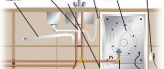
Sewage scheme in the apartment
In the first case, there is no slope of the line or it is not enough to move the liquid by gravity. As a result, the flow rate decreases, which is why dense fractions are not washed away, but remain on the inner walls of the pipes. There is a gradual accumulation of sediment, which develops into a blockage.
Partial wastewater with impurities of fractions of different densities is retained on the walls of the pipeline, as a result of which the pipeline becomes covered with silt and begins to emit unpleasant odors that penetrate back into the room. Therefore, you will have to regularly clean the sewer in a private house or apartment where the installation of the system was carried out in violation of the requirements.
Excessive tilting of the system can also create the prerequisites for frequent cleaning for preventive purposes. An intense flow of liquid at high speed will not be able to capture solid particles from the walls and wash them away. Moreover, in the process of moving water, fecal fractions will be layered and pressed on the walls of the sewer. In this case, all shut-off valves and pipe joints will be subject to severe stress, which increases the risk of failure. Therefore, it is very important to adhere to the recommended parameters prescribed in SNiP documents.
Construction of storm drainage
In general, installation work on the installation of storm drains is carried out in the same way as when laying external pipelines of a conventional sewer system.
Selection of pipes for the underground part of the pipeline
If external storm sewer networks are installed, SNiP allows the use of the following types of pipes:
- Asbestos-cement;
- Steel;
- Plastic.
Asbestos cement is a traditional material used for the construction of external sewerage pipelines, including stormwater. The disadvantages of the material include its high fragility and significant weight (a meter of pipe with a diameter of 100 mm weighs more than 24 kg). Steel pipes have much less weight (a meter of pipe weighs about 10 kg), but they are prone to corrosion, so it is not profitable to use them for the construction of storm drains.
Recently, plastic pipes have been used to construct storm drains. They are light (a meter weighs no more than 5 kg), but durable and resistant to corrosion. In addition, they are easy to connect and do not require welding. Can be used:
- PVC pipes, if external networks are installed, then for their construction you need to use a special type of pipes, they are painted orange;
- Multilayer polymer pipes. Today this is the best option. These pipes have a smooth inner surface, so there is no hydraulic resistance.
Installation of the roofing part
The work goes like this:
- Openings are made in the ceilings for installing rainwater inlets, and all junctions are carefully sealed.
- Drainage pipes are strengthened when constructing a point system or trays when installing a linear storm drain.
- Install drain risers or pipes.
- A unit is assembled for discharging water into a collector or discharging into tray systems.
- All devices are attached to walls and ceilings using clamps. Places for installing clamps are planned in advance, not forgetting to follow the recommended slope values.
Laying the underground part
- Installation begins with the installation of trenches. When constructing systems such as storm sewers, the depth of installation is most often determined not by the depth of freezing, but by the experience of operating the systems at the construction site.
- Trenches are dug with a slope, that is, their depth should gradually increase.
- At the bottom of the trenches there is a sand cushion, the layer height is 20 cm.
- A pit is being prepared for installing the collector.
- Pipes should be laid in the prepared ditches, the pipes should be connected to each other and connected to the collector using conventional fittings.
- If the sewer network consists of a single branch more than 10 meters long, then it is worth planning to install a manhole in the middle of it. Such wells should be installed at network branch points.
- Sand traps are installed at the junction of water inlet gutters and stormwater pipe systems.
- Now all that remains is to backfill the trenches and cover the open structures (trays) with gratings on top.
Collector installation rules
When arranging a network of pipes or storm drainage trays, you must follow some rules
- Thus, the communication device requires not only laying a sand and gravel cushion in the trench, but also pouring concrete mortar to securely fix the collector.
- When installed, the entire system must be equipped with special sand traps that will clean the water from small debris and prevent silting of the entire network. Such tanks are installed at the point where water enters from storm water inlets or gutters into a common sewer pipe.
Important: sand trap baskets require regular cleaning. If there is a tortuous communication line, it is worth placing inspection wells at all turns
By the way, they can also play the role of sand traps. If a straight network with a length of more than 10 meters is being constructed, then an inspection well is also installed on each 10 m segment.
If there is a tortuous communication line, it is worth placing inspection wells at all turns. By the way, they can also play the role of sand traps. If a straight network with a length of more than 10 meters is being constructed, then an inspection well is also installed on each 10 m segment.
https://youtube.com/watch?v=mYqthJUxyLc
Studying the standards
All construction and installation work must be carried out in accordance with current standards, rules and regulations. Such requirements are specified in GOSTs and SNiPs. The same applies to the installation of storm drains. SNiP 2.04.03-85 is in force here, which is called “Sewerage. External structures and networks."
Some paragraphs of this document indicate the recommended depth for laying stormwater pipes. According to them, installation should be carried out:
- for pipes with a cross-section of up to 500 mm, at least 30 cm below the ground freezing level;
- for pipes with a cross-section of more than 500 mm - at least 50 cm.
But all these points regarding the depth of occurrence are rather advisory in nature. Their use lies with the conscience of installers and builders. According to SNiP, installation must be carried out based on the experience of operating sewer systems in each specific region. In general, the minimum depth should be at least 70 cm from the surface.
What is a storm drain
Storm drainage is an extensive engineering system that drains melt and rainwater from buildings. There are no major organic inclinations in the building, which makes it fundamentally different from everyday types. In addition to moisture, a lot of silt, solid debris and sand enter the sewer, which leads to rapid clogging. The design is easy to open and remove possible blockages.
Stormwater is created in the form of a gravity system. In order for moisture to move inside an engineering structure, the correct slope of pipes and trays is needed. The angle of rainwater drainage often depends on the requirements of SNiP and the technical characteristics of conductive parts. The structure consists of:
- external channels;
- filters;
- inspection wells;
- pipes;
- collectors.
Each part works only as part of an engineering system. To remove large debris, install a grate. In structures without additional protection, serious blockages from dirt and sand quickly arise.
The type and structure of storm drains depends on the intensity of runoff. In small areas, a point system is sufficient. The liquid from the storm drain is gradually absorbed into the soil, so the structures are made without a bottom. Wells are located next to buildings. To ensure proper operation in the model, it is not the depth that is important, but the inclination of the pipeline and trays.
Linear systems are used in regions with high rainfall. The elements collect and discharge wastewater into reservoirs and ditches. According to the structure of the structure, there are underground (closed) and external (open). Performance depends on the depth of the storm drain and the correct slope.
Formulas for hydraulic calculation of storm networks
In order to calculate the diameter of a storm sewer pipe, it is necessary to determine the average flow of rainwater, which depends on the climatic conditions in a particular area.
The maximum flow rate (intensity) of rainwater is calculated using the formula:
Qr = q20·Ψ·F
Where:
q20 – estimated rain intensity for 20 minutes;
Ψ – coefficient of moisture absorption by a certain type of coating (roofing – 1.0; asphalt – 0.95; concrete – 0.85; crushed stone – 0.4);
F – surface area (in hectares) on which drainage is planned.
Rain intensity map for determining q20 coefficient
For the hydraulic calculation of the storm drainage network, it is necessary to make an adjustment for the filling factor of the free pipeline when a pressure regime occurs (β). Thus, the flow of rainwater is calculated as
Q = Qr·β
Coefficient β is determined from the table:
| Rain duration indicator n | 0,7 | 0,6 | 0,5 | 0,4 |
| β coefficient value | 0,65 | 0,7 | 0,75 | 0,8 |
In turn, the parameter n depends on the geographical location of the object:
| Area | Parameter value n |
| Coast of the Barents and White Seas | 0,4 |
| North of the European part of the Russian Federation | 0,48 |
| Center and west of the European part of the Russian Federation | 0,59 |
| Western slope of the Urals | 0,59 |
| Lower Don and Volga | 0,57 |
| Lower Volga region | 0,66 |
| Central Siberia | 0,47 |
| Eastern Siberia | 0,52 |
| Western Siberia | 0,58 |
| Altai | 0,48 |
| Coast of the Sea of Okhotsk | 0,31 |
If the terrain slope is 1-3 cm per 1 m, then the β coefficient must be increased by 15%. For a larger slope, this parameter is taken equal to 1.
Calculation of pipe filling degree
What pipe diameter should I choose for laying external sewerage? This question should stand alongside other factors when creating a project. Because the rate of water drainage depends on this. The water filling coefficient is measured in centimeters per meter; the degree calculation cannot be used here due to the fact that errors will arise, for example: the length of the pipeline is too large and ultimately even a small discrepancy will lead to the fact that the elements will not converge and will be located in different planes .
The value that will be optimal for the operation of the sewerage system is calculated by the formula, it sounds like this: we divide the sewerage rise level “H” by the diameter of our sewer pipe “D”. The value we should get should vary between 0.5 and 0.6. If we get 0 during the calculation, this will mean that the pipe will be constantly empty. If we have the final number 1, then the pipe will be constantly and completely flooded with water. Which will have a detrimental effect on the system. The formula itself looks like this
Y=H/D
- H – height;
- D – diameter;
- Y – filling values.
If you use PVC pipes, then its filling should be 0.5. The reason for this is its inner surface; it has no roughness. Unlike asbestos or iron pipes, they have the highest degree of roughness, for this value it is 0.6.
The value described above will allow wastewater to pass at an average speed of 0.7 m/s. This will keep solids suspended, preventing them from sticking to the walls of the sewer pipes.
Rainwater drainage via other networks
Private real estate projects traditionally include other communication networks along with storm drainage. Domestic sewerage and drainage systems are also part of household communications. The principle of their operation differs little from the functioning of storm drains, in which owners of private houses often see the possibility of using these networks.
Meanwhile, the combination of storm sewerage with a domestic or drainage drainage scheme is prohibited by SNiP. The ban on combining different types of sewage systems is due to obvious factors. Thus, provided that rainwater is discharged into the domestic sewer system and taking into account the high intensity of precipitation, the normal level of sewerage is increased several times.
Flooding of working wells leads to blockage of household and fecal wastewater. Mud deposits and natural debris flow into the domestic sewage system. As a result, after the next rainstorm, the organizers of the structure will have to clean the system.
Combining a stormwater system with a drainage main threatens to result in even more disastrous results. Overflow of drainage due to violation of design loads leads to flooding of the building foundation. Frequent flooding disrupts the structure of the soil, which causes displacement of foundation blocks, and in the future can lead to the destruction of the building.
Professional design
Not everyone can carry out an independent storm drain calculation.
In addition, if the owner of a private residential plot has the right to make a mistake, he can design a sewer system at his own peril and risk
To organize even a small enterprise, to draw up plans for the improvement of urban or courtyard areas, carefully calculated, technically sound projects are required that fully comply with all existing sanitary and construction standards.
Such design and survey work is carried out by special organizations that have state certification to carry out activities of this kind
.
When contacting specialists, the customer presents them with a number of documents that will form the basis of the technical specifications:
- Topographical diagram of the territory from which stormwater is expected to be drained.
- Geological survey data containing information about the nature of the soils on the site.
- General development plan.
- If you plan to discharge into a centralized collector system
, the technical conditions of the water utility services for connection. - Sanitary standards for water purification if it is intended to be discharged into natural reservoirs or drainage fields.
- Possible customer wishes for organizing the accumulation of collected water.
The result of the designers’ work is a package of documents, which includes:
- General information about the site being developed and storm drainage.
- Detailed schematic diagram of storm drainage.
- A scaled drawing-plan of the site with reference to the locations of all elements of the storm drain. In essence, it is a ready-made installation instruction for further work.
- Detailed specification of the equipment required according to the technical specifications.
- A full estimate for the purchase of the required materials and construction, installation and commissioning works.
The finished storm sewer project is subject to mandatory approval from water utility companies, state technical supervision authorities, the sanitary-epidemiological service, and the environmental control service in charge of the state of water resources.
Only after the project has been fully approved by all regulatory authorities can its practical implementation begin.
Some design organizations take on the entire process of approving the project they have developed.
The design process is complex, but there are no trifles in this matter.
In order for the storm sewer to fully fulfill its functions, so as not to incur penalties for violations of environmental legislation, it is better to entrust the development of the project to experienced specialists whose qualifications are not in doubt.
Individual slope calculation
Laying sewer pipes with your own hands in a private house is carried out according to the standards that appear in SNiP. But you can calculate the parameters for the arrangement of sewerage and water supply networks yourself. To do this, use the following formula:
V√H/D ≥ K, where:
- K is a special coefficient that takes into account the properties of the material that was used in the manufacture of the pipe;
- V – speed of passage of wastewater;
- H – pipe filling capacity (flow height);
- D – section (diameter) of the pipe.
The slope of sewer pipes can be calculated independently
Explanations:
- coefficient K, for pipes made of smooth materials (polymer or glass), should be equal to 0.5, for a metal pipeline - 0.6;
- indicator V (flow velocity) - for any pipeline is 0.7-1.0 m/s;
- H/D ratio - indicates the filling of the pipe, and should have a value from 0.3 to 0.6.
Internal and external sewer systems
When laying sewer and water supply networks in a private house, you should take into account some features that are determined by the location of their individual sections.
Internal systems
When installing sewer pipes in a private house, two diameters are mainly used - 50 mm and 110 mm. The first is for drainage, the second is for the toilet. The laying of the sewer pipe should be carried out in accordance with the following recommendations:
- turning the pipeline (if it is horizontal) should not be done at an angle of 90 degrees. To change the direction, it is better to install the bends at an angle of 45 degrees, this greatly facilitates the passage of the main flow and reduces the likelihood of accumulation of solid particles;
- in places where the system turns, fittings should be installed for inspection and ease of cleaning or dismantling in case of clogging;
- in short individual sections, it is permissible to increase the slope, exceeding the recommended norm. Such a short sewer branch can be a pipe connecting the toilet to the riser;
- in each individual section, the slope of the pipeline must be uniform, without sudden changes, because their presence can create conditions for the occurrence of a water hammer, the consequences of which will be the repair or dismantling of an already operating system.
External (external) systems
Proper laying and installation of sewer pipes is necessary not only inside, but also outside a private home, from the point of exit of the internal sewerage system to the septic tank.
Therefore, you should pay attention to the following points:
- laying of sewer networks is carried out in trenches with a depth of 0.5 to 0.7 meters. The depth of penetration depends on the characteristics of the soil and is adjusted to specific conditions;
- when preparing trenches, sand should be used at the bottom to be able to establish the correct slope by adding it;
- highlight the pre-calculated slope (per linear meter) as a guide from the cord stretched between the driven pegs. This will avoid unnecessary subsidence or elevation of the sewer system in certain areas;
- After laying the pipes at the bottom of the trench, check again for the correct slope and, if necessary, correct it using a sand cushion.
Calculation of slope for an apartment
To install a sewer system for a sink, washbasin and bathroom, you need to choose pipes with a diameter of 40-50 mm. There should be a slope of no more and no less than 2.5-3.5 cm per meter. The minimum value of the slope coefficient per meter is 0.012, and the standard value is 0.02. For a toilet, the required slope is 85-100 mm, and for a common riser - 100 mm. To calculate the slope coefficient, the formula is used:
V*√(H/d)>K,
where K is the coefficient for plastic and glass pipes 0.5, and for others 0.6,
N is the coefficient of how quickly the pipeline fills,
V is the speed of fluid movement along the line,
D is the internal diameter of the pipe.
To correctly set the level of inclination of the pipe in the apartment, it is enough to use a regular ruler.
How to calculate occupancy levels
For plastic and cast iron pipes, it is mandatory to calculate the level of water filling. Thanks to this indicator, you can find out at what speed the water should move so that it cannot become clogged. And of course, the exact value of the slope per meter depends on this indicator. To calculate the filling rate, you need to divide the water level in the pipe by the diameter.
The minimum indicator according to SNIPA is 0.3, and the maximum is 1. But, in practice, this occupancy rate is in the range of 0.3-0.6. It is the optimal one.