Why is a hydraulic calculation of a water supply network performed? What parameters exactly need to be calculated? Are there any simple calculation schemes available for a beginner? Let’s say right away: this material is aimed primarily at owners of small private houses; Accordingly, we do not need to determine such parameters as the probability of simultaneous use of all plumbing fixtures in the building.
Like any engineering system, water supply needs calculation.
What is calculated
Hydraulic calculation of internal water supply system comes down to determining the following parameters:
- Estimated water consumption in individual sections of the water supply system.
- Water flow rates in pipes.
Hint: for internal water supply systems, speeds from 0.7 to 1.5 m/s are considered the norm. For a fire water supply, the permissible speed is up to 3 m/s.
- The optimal diameter of the water supply system, providing an acceptable pressure drop . As an option, the pressure loss can be determined with a known diameter of each section. If, taking into account losses, the pressure on plumbing fixtures is less than normal, the local water supply network needs to install a pumping system.
A simple experiment clearly demonstrates the drop in pressure in the water supply.
Features of the cottage layout
How, in fact, is the water supply system in a private house less complicated than in an apartment building (obviously, except for the total number of plumbing fixtures)?
There are two fundamental differences:
- In warm water, in most cases, there is no need to provide constant circulation through risers and heated towel rails.
In the presence of circulation connections, the calculation of the warm water supply network becomes noticeably more complicated: the pipes need to pass through themselves not only the water disassembled by the residents, but also the continuously circulating weights of water.
In our case, the distance from the plumbing fixtures to the boiler, pump or freeway connection is small enough so as not to pay attention to the speed of supply of hot water to the tap.
Fundamentally important: For those who have not encountered hot water circulation circuits, in modern multi-apartment buildings the warm water supply risers are connected in pairs. Due to the difference in pressure on the taps created by the retaining washer, water continuously circulates through the risers. This ensures rapid supply of hot water to the mixers and year-round heating of heated towel rails in bathrooms.
Water consumption
Water consumption standards for individual plumbing fixtures can be found in one of the annexes to SNiP 2.04.01-85, which regulates the construction of internal water supply and sewerage networks. We present part of the corresponding table.
| Device | Cold water consumption, l/s | Total consumption (hot water and hot water), l/s |
| Washbasin (water tap) | 0,10 | 0,10 |
| Washbasin (mixer) | 0,08 | 0,12 |
| Sink (mixer) | 0,08 | 0,12 |
| Bath (mixer) | 0,17 | 0,25 |
| Shower stall (mixer) | 0,08 | 0,12 |
| Toilet with cistern | 0,10 | 0,10 |
| Toilet with direct water supply | 1,4 | 1,4 |
| Irrigation tap | 0,3 | 0,3 |
In the case of the expected simultaneous use of several plumbing fixtures, the consumption is summed up. So, if at the same time as using the toilet on the first floor there is supposed to be a shower on the second floor, it would be quite logical to add up the water flow through both plumbing fixtures: 0.10 + 0.12 = 0.22 l/s.
When connecting devices in series, the water consumption is summed up.
A special case
For fire water supply systems, the flow rate is 2.5 l/spa per stream. At the same time, the estimated number of jets per fire hydrant during fire extinguishing is quite predictably determined by the type of building and its area.
The photo shows a fire hydrant.
| Building parameters | Number of jets when extinguishing a fire |
| Residential building with 12 - 16 floors | 1 |
| The same, with a corridor length of more than 10 meters | 2 |
| Residential building with 16 - 25 floors | 2 |
| The same, with a corridor length of more than 10 meters | 3 |
| Management buildings (6 – 10 floors) | 1 |
| The same, with a volume of more than 25 thousand m3 | 2 |
| Management buildings (10 or more floors, volume up to 25,000 m3) | 2 |
| The same, volume more than 25 thousand m3 | 3 |
| Public buildings (up to 10 floors, volume 5 - 25 thousand m3) | 1 |
| The same, volume more than 25 thousand m3 | 2 |
| Public buildings (more than 10 floors, volume up to 25 thousand m3) | 2 |
| The same, volume more than 25 thousand m3 | 3 |
| Enterprise administrations (volume 5 - 25 thousand m3) | 1 |
| The same, volume more than 25,000 m3 | 2 |
Valtec “Sputnik” software package
The Valtec “Sputnik” software package is intended for use in the housing and communal services sector (management companies, homeowners' associations) and industry. The intuitive interface makes it easy for users to quickly learn. A number of special reports for management companies (homeowners associations, resource supply organizations) and integration with accounting programs (1C) make it easy to generate payment receipts. The control center includes reports that allow you to track emergency situations, unauthorized access to resources, and requests from subscribers from your personal account.
Integration into the Housing and Public Utilities GIS has been introduced to simplify reporting in organizations.
- Main features:
- Collection of readings from metering devices, event sensors, remote resource limitation
- Online emergency monitoring
- Data storage
- Generating special reports
- Integration with related software products used in the organization’s business processes (1C, video surveillance, POS, etc.)
- Open API
- Recommendations for saving resources
To familiarize yourself with the program's capabilities: Login: demo Password: demo
In the case of a comprehensive supply of metering devices and dispatch systems, a license file that allows you to fully work with the program is issued free of charge. The server is formed on the customer's side.
As an additional paid service, it is possible to use a Valtec remote cloud server.
For commissioning, commissioning of a facility or testing of dispatch system equipment, a free test license file valid for 1 month is provided.
For details on obtaining a test license, please contact the managers working in your region.
Flow rate
Let's assume that our task is a hydraulic calculation of a dead-end water supply network with a known peak flow through it. We need to determine the diameter that will ensure an acceptable flow rate through the pipeline (remember, 0.7-1.5 m/s).
High flow speed causes hydraulic noise.
Formulas
Water consumption, flow rate and pipeline size are linked to each other by the following sequence of formulas:
S = π r ^2, where:
- S is the cross-sectional area of the pipe in square meters;
- π is the number “pi”, taken equal to 3.1415;
- r is the radius of the internal section in meters.
Useful: for steel and cast iron pipes, the radius is usually taken equal to half of their DN (nominal bore). Most plastic pipes have an internal diameter one step smaller than the nominal external one: for example, a polypropylene pipe with an external diameter of 40 mm has an internal diameter of approximately 32 mm.
The nominal diameter approximately corresponds to the internal diameter of the steel pipe.
Q = VS, where:
- Q—water consumption (m3);
- V—water flow velocity (m/s);
- S is the cross-sectional area in square meters.
Example
Let's perform a hydraulic calculation of a fire water supply for one jet with a flow rate of 2.5 l/s.
As we have already found out, in this case the speed of the water flow is limited to m/s.
- We recalculate the flow rate into SI units: 2.5 l/s = 0.0025 m3/s.
- We calculate the minimum cross-sectional area using the second formula. At a speed of 3 m/s it is equal to 0.0025/3=0.00083 m3.
- We calculate the radius of the internal section of the pipe: r^2 = 0.00083/3.1415 = 0.000264; r = 0.016 m.
- The internal diameter of the pipeline must therefore be at least 0.016 x 2 = 0.032 m, or 32 millimeters. This corresponds to the parameters of a DN32 steel pipe.
Please note: when obtaining intermediate values between standard pipe sizes, rounding is performed up. The price of pipes with diameters that differ by one step does not vary too much; Meanwhile, a reduction in diameter by 20% entails an almost one and a half times drop in the throughput of the water pipeline.
The throughput of the first and third pipes differs fourfold.
VALTEC SET software package
VALTEC SET is a calculation and graphic program for the design of radiator and underfloor heating systems (CO module), as well as for the design of cold and hot water supply systems (H2O module) using VALTEC equipment. The program was developed by SANKOM Sp. z oo based on the latest version of the Audytor CO program – 7.2. The product allows you to design heating and water supply systems, and perform a full range of hydraulic and thermal calculations.
Get CO Basic module keys
Get H2O Basic module keys
Loss of pressure
Formulas
The instructions for calculating head loss over a section of known length are quite simple, but require knowledge of a fair number of variables. Fortunately, if desired, they can be found in reference books.
The formula looks like H = iL(1+K).
In it:
- H is the desired pressure loss value in meters.
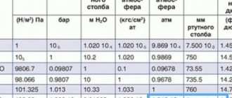
Reference: an excess pressure of 1 atmosphere (1 kgf/cm2) at atmospheric pressure corresponds to a water column of 10 meters. To compensate for a pressure drop of 10 meters, therefore, the pressure at the entrance to the water distribution network must be increased by 1 kgf/cm2.
- i is the hydraulic slope of the pipeline.
- L is its length in meters.
- K is a coefficient depending on the purpose of the network.
The formula is greatly simplified. In practice, pipeline bends and shut-off valves also cause a drop in pressure.
Some elements of the formula clearly require comment.
The easiest way is with the coefficient K. Its values are included in the SNiP we have already mentioned, number 2.04.01-85:
| Purpose of the water supply | Coefficient value |
| Household drinking water | 0,3 |
| Industrial, economic and fire protection | 0,2 |
| Industrial and fire protection | 0,15 |
| Fireproof | 0,1 |
But the concept of hydraulic slope is much more complicated. It reflects the resistance that the pipe provides to the movement of water.
The hydraulic slope depends on three parameters:
- Flow rates. The higher it is, the greater the hydraulic resistance of the pipeline.
- Pipe diameter. Here the relationship is inverse: a decrease in cross-section leads to an increase in hydraulic resistance.
- Wall roughness. It, in turn, depends on the pipe material (steel has a less smooth surface compared to polypropylene or HDPE) and, in some cases, on the age of the pipe (rust and lime deposits increase roughness).
Fortunately, the problem of determining the hydraulic slope is completely solved by the table for hydraulic calculation of water pipes (Shevelev’s table). It gives values for different materials, diameters and flow rates; In addition, the table contains correction factors for old pipes.
Shevelev tables.
Let us clarify: age adjustments are not required for all types of polymer pipelines. Metal-plastic, polypropylene, ordinary and cross-linked polyethylene do not change the surface structure throughout the entire period of operation.
The size of Shevelev's tables makes it impossible to publish them in their entirety; however, for your reference, we will provide a short excerpt from them.
Here is the reference data for a plastic pipe with a diameter of 16 mm.
| Flow in liters per second | Speed in meters per second | 1000i (hydraulic gradient for 1000 meters) |
| 0,08 | 0,71 | 84 |
| 0,09 | 0,8 | 103,5 |
| 0,1 | 0,88 | 124,7 |
| 0,13 | 1,15 | 198,7 |
| 0,14 | 1,24 | 226,6 |
| 0,15 | 1,33 | 256,1 |
| 0,16 | 1,41 | 287,2 |
| 0,17 | 1,50 | 319,8 |
When calculating the pressure drop, it must be taken into account that most plumbing fixtures require a certain excess pressure for normal operation. Thirty-year-old SNiP provides data for outdated plumbing fixtures; more modern models of household and sanitary equipment require an excess pressure of at least 0.3 kgf/cm (3 meters of pressure) for normal operation.
The sensor will not allow the flow heater to turn on when the water pressure is below 0.3 kgf/cm2.
However: in practice, it is better to take into account a slightly higher excess pressure - 0.5 kgf/cm2. The reserve is needed to compensate for unaccounted losses on the connections to the devices and their own hydraulic resistance.
Examples
Let's give an example of a hydraulic calculation of a water supply system done by ourselves.
Let's assume that we need to calculate the pressure loss in a household plastic water supply with a diameter of 15 mm with a length of 28 meters and a maximum permissible water flow speed of 1.5 m/s.
Pipes of this size are most often used for distributing water within an apartment or small cottage.
- The hydraulic slope for a length of 1000 meters will be 319.8. Since the head drop formula uses i rather than 1000i, this value should be divided by 1000: 319.8 / 1000 = 0.3198.
- The K coefficient for drinking water supply will be equal to 0.3.
- The formula as a whole will take the form H = 0.3198 x 28 x (1 + 0.3) = 11.64 meters.
Thus, we will have an excess pressure of 0.5 atmospheres at the end plumbing fixture at a pressure in the main water supply of 0.5+1.164=1.6 kgf/cm2. The condition is quite feasible: the pressure in the line is usually not lower than 2.5 - 3 atmospheres.
By the way: tests of the water supply system during commissioning are carried out at a pressure at least equal to the working pressure with a coefficient of 1.3. The report of hydraulic testing of the water supply system must include notes on both their duration and test pressure.
Sample hydraulic test report.
Now let's do the reverse calculation: determine the minimum diameter of the plastic pipeline that provides acceptable pressure at the end mixer for the following conditions:
- The pressure in the route is 2.5 atmospheres.
- The length of the water pipeline to the end mixer is 144 meters.
- There are no diameter transitions: the entire internal water supply will be installed in the same size.
- Peak water flow is 0.2 liters per second.
So let's get started.
- The permissible pressure loss is 2.5-0.5 = 2 atmospheres, which corresponds to a pressure of 20 meters.
- Coefficient K in this case is also 0.3.
- The formula will thus look like 20=iх144х(1+0.3). A simple calculation will give a value of i of 0.106. 1000i, accordingly, will be equal to 106.
- The next stage is to search the Shevelev table for the diameter corresponding to 1000i = 106 at the desired flow rate. The closest value—108.1—corresponds to a polymer pipe diameter of 20 mm.
The relationship between the internal and external diameter of a polypropylene pipeline.
Pressure loss calculation
The operating pressure in the pipeline is the higher excess pressure at which the specified mode of the technological process is ensured. The minimum and maximum pressure values, as well as the physical and chemical properties of the working medium, are the determining parameters when calculating the distance between the pumps pumping the media and the production capacity.
Calculation of losses due to pressure drop in the pipeline is carried out according to the equation:
VALTEC CO 3.8. Heating system design software
VALTEC CO is a calculation and graphic program for designing radiator and underfloor heating systems using VALTEC equipment, developed by SANKOM Sp. z oo based on the latest version of the Audytor CO program – 3.8. The product allows you to design and regulate heating systems, and perform a full range of hydraulic and thermal calculations. The program is certified for compliance with the current construction standards of the Russian Federation and the requirements of the Voluntary Certification System of NP "ABOK" (
).
How water supply and sewerage are designed
Design engineers are involved in the design of water supply and sewerage networks.
It is not allowed to deviate from the plan during construction. The design of water supply and sewerage systems is carried out in stages. Collect initial information about the object: general plan with communications, geological characteristics, technical conditions. Based on the data obtained, technical specifications are formed and a project is drawn up.
Project development solves the following tasks:
- Calculation of water consumption, required water pressure, waste volume.
- Drawing up a water supply and sewerage plan.
- Selection of materials and equipment.
First, determine the source of drinking water: central water supply, well or borehole. If city networks are not connected, choose a suitable method for obtaining hot water: a heat exchanger, an electric water heater or a gas boiler.
Designate a location for installing a septic tank if there is no connection to a public sewer system. The septic tank is designed at a distance of 30 m from the well, and the main sewer riser is located at the wall closest to it. Draw an external plan of water supply and sewerage to the point of entry into the foundation of the building.
Draw up a drawing of the internal wiring of water and drain pipes, indicating the lengths, diameters, and installation points of plumbing equipment. Network wiring projects for multi-storey buildings are carried out on one or more vertical risers.
The number of plumbing fixtures and users determines the required pressure, water consumption, and drain volume. These characteristics are calculated, pipeline diameters and pumping station parameters are set.
The diameter of the main outer drain pipe determines the slope angle:
- Ø 110 mm – 0.02
- Ø 160 mm – 0.008
It is not allowed to decrease or increase the drain slope angle, since the transporting capacity of the liquid is maximum if the calculated value is observed.
The selection of materials and equipment is the final stage of water supply and sewerage design. Materials are selected taking into account operating conditions, network load, and price restrictions.
The architects include in the project the possibility of modernizing, expanding, and repairing the complex in the future. This allows you to eliminate breakdowns and install new equipment during operation without extra costs.
The finished water supply and sewerage project contains floor drawings, an explanatory note with calculations, and a specification of materials.
VHM-T Service. Program for working with VALTEC heat meters
- The VHM-T Service program is designed to work with VALTEC VHM-T heat meters in terms of:
- reading current meter readings and characteristics;
- working with daily, monthly and annual archives;
- generation of thermal energy consumption accounting sheets;
- settings of date, time and automatic transition to summer/winter time (if necessary);
- counter settings for operation in automated data accounting systems.
Work computer software requirements
- operating system Windows XP Service Pack 3 (32/64 bit) or higher;
- Visual C++ Redistributable Packages for Visual Studio 2013 (free download available from microsoft.com). As a rule, these packages are already present in versions of Windows 7 and higher with the latest updates.
The interaction of the working computer with the heat meter is carried out through an optoelectronic sensor with the appropriate drivers installed in the system.
Setting up communication between the program and the meter
- Connect the optoelectronic sensor to the computer.
- On the front panel of the heat meter, press and hold the button (about 8 seconds) until the “=” symbol appears in the lower right corner of the screen.
- Bring the optoelectronic sensor to the opto-receiver of the meter on the front panel.
- Give a command to establish a connection in the program.
— Windows XP/Server 2003/Vista/7/8/8.1 (v6.7)
To activate the program, you must register again. The activation key is sent to the user's email address within 1-2 days.
If you have any questions about working with the program, you can ask them at:
Programs for old-style counters
Valtec “Sputnik” equipment configurator
Configurator software is a modular configurator for various metering devices and equipment. Allows commissioning of the Valtec “Sputnik” automated energy metering system.
- The configurator includes the following modules:
- polling of metering devices via radio channel using radio modem VT.WRM.MASTER.0
- module for reading data from VT.WRM hubs
- module for configuring wireless pulse counter-recorder GSM/GPRS VT.WLR.GSM
- module for configuring a wireless pulse counter-recorder with a radio channel (LoRAWAN 868 MHz) VT.LR
- module for configuring pulse counter-recorder SIPU (RS485/M-Bus) VT.MB/ VT.RS
Selection of materials
Pipes made of copper, metal-plastic, and polypropylene are popular for internal water supply.
A water supply and sewerage project includes the selection of pipelines with the required parameters. The industry produces a wide range of pipes for drinking water and waste liquids.
Pipeline materials:
- metal-plastic,
- cast iron,
- steel,
- copper,
- polyethylene,
- polypropylene,
- polyvinyl chloride,
- fiberglass,
- asbestos,
- reinforced concrete.
The most common products are made of polymers, metal-plastic, and stainless steel. Internal water pipes are made of PPRC polypropylene, metal-plastic, PEX cross-linked polyethylene, corrugated stainless steel. Internal drain pipes are made from PP polypropylene, gray PVC and HDPE high density polyethylene.
For external water supply systems, products made of PE polyethylene and polyethylene with a PE-RC protective layer are used. External drainage systems are made of orange polyvinyl chloride, corrugated polyethylene and corrugated two-layer PP polypropylene.
The designer decides on the type of pipe, based on the technical specifications of the project, the advantages and disadvantages of the material, and also takes into account the wishes of the customer.