One of the most common elements of a home's electrical system is the electrical outlet. On the diagram it may look like different symbols, which depend on the type and design of this device.
The most important stage in arranging electrical wiring is drawing up a plan for the placement of all its elements. Proper application of all components of the electrical network to the electrical diagram ensures correct planning of the required amount of materials, as well as a high level of electrical safety. A correctly drawn up diagram greatly facilitates the selection of the types of equipment needed.
The electrical wiring plan is drawn up taking into account the scale of the premises and the features of its layout.
Advice! Traditionally, to draw up such drawings, a single-line diagram is used, which allows you to display all the elements of the network without cluttering the drawing with a large number of lines depicting connecting wires.
Guiding Documents
In order to unify the symbols used in electrical circuits, GOST 21.614-88 “Conventional graphic images of electrical equipment and wiring on plans” was adopted back in Soviet times.
In accordance with this document, the simplest geometric shapes are used to designate all elements of the electrical network, making it easy to apply and also identify a particular element on an electrical circuit.
Strict requirements for the execution of such drawings eliminate confusion and double interpretation of all symbols printed on the diagram, which is extremely important when performing installation work in the electrical network.
Introduction
But let's start a little from afar... Every young specialist who comes to design begins either by folding drawings, or by reading regulatory documentation, or by drawing “this” according to this example. In general, normative literature is studied in the course of work and design.
It is impossible to read all the normative literature related to your specialty or even a narrower specialization. Moreover, GOST, SNiP and other standards are periodically updated. And each designer has to monitor changes and new requirements of regulatory documents, changes in the lines of electrical equipment manufacturers, and constantly maintain their qualifications at the proper level.
Remember Lewis Carroll in Alice in Wonderland?
“You have to run as fast as you can just to stay in place, and to get somewhere, you have to run at least twice as fast!”
This is not my way of whining about “how hard the life of a designer is” or boasting “look, what an interesting job we have.” That's not what we're talking about now. Given such circumstances, designers adopt practical experience from more experienced colleagues; they simply know how to do many things correctly, but do not know why. They work according to the principle “That’s the way it is here.”
Sometimes these are quite basic things. You know how to do it right, but if they ask “Why is this?”, you won’t be able to answer right away, referring at least to the name of the regulatory document.
In this article, I decided to structure the information regarding symbols, sort everything out, and collect everything in one place.
Designations of elements of an open installation
The simplest two-pole electrical socket of open installation without a grounding contact is depicted on the electrical diagram in the form of a semicircle with a line drawn perpendicular to its convex part.
The designation of a double socket differs from the previous one in the presence of two parallel lines. The graphic symbol corresponding to a three-pole product is a semicircle, the convex part of which is adjacent to three lines converging at one point and arranged like a fan.
To designate a socket with a grounding contact, a horizontal line is added to its image, which is tangent to the top point of the semicircle.
Basic UGO for single-line diagrams of electrical panels
| UGO | Name |
| Thermal relay | |
| Contactor contact | |
| Switch - load switch | |
| Automatic - circuit breaker | |
| Fuse | |
| Differential circuit breaker | |
| RCD | |
| Voltage transformer | |
| Current transformer | |
| Switch (load switch) with fuse | |
| Motor protection circuit breaker (with built-in thermal relay) | |
| A frequency converter | |
| Electricity meter | |
| Normally closed contact with reset button or other push-button switch, with reset and opening by means of a special actuator of the control element | |
| Normally closed contact with push-button switch, with reset and opening by retracting the control button | |
| Normally closed contact with push-button switch, reset and open by pressing the control button again | |
| Normally closed contact with push-button switch, with automatic reset and opening of the control element | |
| Delayed closing contact that initiates upon return and operation | |
| Delayed closing contact which only operates on return | |
| Delayed closing contact which is only initiated when triggered | |
| Delayed closing contact which is actuated by return and tripping | |
| Delayed closing contact which only operates on return | |
| Delayed closing contact that only switches when triggered | |
| Timing relay coil | |
| Photo relay coil | |
| Pulse relay coil | |
| General designation of a relay coil or contactor coil | |
| Indication lamp (light), lighting | |
| Motor drive | |
| Terminal (separable connection) | |
| Varistor, surge arrester (surge suppressor) | |
| Arrester | |
Socket (plug connection):
| |
| A heating element |
Sockets for hidden electrical wiring
Concealed wiring is the most common type of home electrical network. To install it, devices are used that are built into the wall using special mounting boxes.
USEFUL INFORMATION: Modular sockets on DIN rail
The only difference between the designation of such rosettes and the above figure is the perpendicular, lowered from the middle of the straight segment to the center of the circle.
Images of wiring lines and conductors
Table 1
| Name | Image | Size, mm |
| 1. Wiring line | ||
| General image It is allowed to indicate wiring data (type of current, voltage, material, installation method, wiring mark, etc.) above the line image. | Thickness 1.0 | |
| For example. 110V DC circuit | Same | |
| It is allowed to indicate the number of conductors in a line with serifs. | ||
| For example. Line consisting of three conductors | ||
| 1.1. Control line | ||
| 1.2. Emergency evacuation and security lighting network line | ||
| 1.3. Voltage line 36 V and below | ||
| 1.4. Grounding and grounding line | ||
| 1.5. Grounding switches | ||
| 1.6. Metal structures used as grounding and grounding lines | ||
| 2. Laying wires and cables | ||
| 2.1. Open laying of one conductor | ||
| 2.2. Open routing of multiple conductors | ||
| 2.3. Open laying of one conductor under the ceiling | ||
| 2.4. Open laying of several conductors under the ceiling | ||
| 2.5. Laying on the cable and its end fastening | ||
| 2.6. Wiring in the tray | ||
| 2.7. Wiring in a box | ||
| 2.8. Wiring under the baseboard | ||
| 2.9. Cable end | ||
| 3. Vertical wiring | ||
| 3.1. Posting goes to a higher level or comes from a higher level | ||
| 3.2. The posting goes to a lower level or comes from a lower level | ||
| 3.3. The wiring crosses the mark shown on the plan from top to bottom or bottom to top and has no horizontal sections within this plan | ||
| 4. Wiring in pipes General image | ||
| 4.1. Wiring in a pipe laid openly | ||
| 4.2. Wiring in pipes laid openly | ||
| 4.3. The same, if it is necessary to display the dimensions of a group of pipes | ||
| 4.4. Wiring in a pipe laid under the ceiling, platform, indicating the location mark | ||
| 4.5. Wiring in pipes laid under the ceiling | ||
| 4.6. The same, if it is necessary to display the dimensions of a group of pipes | ||
| 4.7. Wiring in a pipe laid hidden (in concrete, in soil, etc.), indicating the location mark | ||
| 4.8. Wiring in hidden pipes | ||
| 4.9. The same, if it is necessary to display the dimensions of a group of pipes | ||
| 4.10. Wiring in a pipe laid from the route mark upwards | ||
| 4.11. Same thing, down | ||
| 4.12. The end of the wiring in the pipe | ||
| 4.13. Wiring in a pipe through the wall | ||
| 4.14. The same, through the ceiling | ||
| 4.15. Separating seal in pipes for hazardous areas | ||
| 4.16. Flexible wiring in a metal hose, flexible input | ||
| 5. Laying busbars and busbars | ||
| General image | Thickness 2.0 | |
| 5.1. Busbar laid on insulators | ||
| 5.2. Package of tires laid on insulators | Thickness 1.0 | |
| 5.3. Busbars or busbar trunking on racks | ||
| 5.4. The same, on suspensions | Same | |
| 5.5. The same, on the brackets | ||
| 5.6. Trolley line | ||
| 5.7. Trolley line sectioning | ||
| 5.8. Tire compensator, trolley |
Note. The image of the mounting location of the busbar according to clauses 5.1-5.5 must correspond to its design position.
6. Images of boxes, panels, equipment boxes, cabinets, panels, consoles are given in Table 2
Devices with increased protection from dust and moisture
The sockets considered do not have a high level of protection against the penetration of solid objects into their housing, as well as moisture. Such products can be used in interior spaces where operating conditions exclude such effects. As for devices intended for installation outdoors or, for example, in bathrooms, according to the accepted classification, their degree of protection should be below IP44 (where the first digit corresponds to the level of protection against dust, the second - against moisture).
Such sockets are indicated on the diagram in the form of a semicircle completely shaded in black. As in the previous case, two-pole and three-pole waterproof sockets are indicated by the corresponding number of segments adjacent to the convex part of the semicircle.
Necessity of the scheme
If we talk about light switches, then the number of poles means how many lines can be switched on in isolation from each other.
As a rule, they are installed at a height of 0.9 meters from the floor level. Basic standards that define conventional images on electrical wiring diagrams Everything related to electrical engineering, electrical engineering, etc.
Like sockets, light switches are included in the design documentation. One line is a two-pole socket, two are a double two-pole socket, three, shaped like a fan, are a three-pole socket. They are indicated by an empty semicircle that does not have any additional lines inside.
A similar designation was introduced for switches. This can be seen in the diagram of such devices.
Regulations
All designations are extremely clear for drawing up a diagram, even for a person without special education. Some modern electrical appliances require not a single-phase, but a three-phase power supply. Symbol of switches In addition to conventional switches, there are pass-through and cross switches, which allow you to control the light from several places.
It goes well with interiors stylized as the eighteenth and nineteenth centuries; in addition, it can serve as a light dimmer. The opposite of the rotary switch is the touch switch. This is necessary for maintaining all the necessary engineering documents when laying electrical wiring in the premises.
If the reference standard is canceled without replacement, then the provision in which a reference is made to it is applied in the part that does not affect this reference. If everything is done correctly, this will allow you to accurately interpret the contents of the drawing. And secondly, there is no need to make grooves for laying wires separately to each switching device; the conductors going to both the socket and the switch are laid in one groove. They are needed not only to ensure long-term operation of electrical appliances, but also for the safety of people when using electricity.
Principles of product classification Structurally, the switch is similar to a plug socket. In the schematic representation of such switching devices, the semicircle inside has a line in the center. Basic logical elements of a computer. Valves. Principle of operation. Designation on the diagram.
Switches
The switch in the diagram is indicated in the form of a circle, to which a line is drawn at an angle of 45 with an inclination to the right side, having one, two or three perpendicular segments at the end (depending on the number of keys of the switch depicted).
The image of the hidden installation switches is the same, only the segments at the end of the inclined line are drawn in both directions from it at the same distance.
Moisture-resistant products are indicated by a black circle.
It is worth paying attention to the image of pass-through switches, which resembles two ordinary switches, mirrored from the center of one circle.
Representation of electrical equipment on plans
Despite the fact that GOST 2.702-2011 and GOST 2.701-2008 take into account this type of electrical circuit as a “layout diagram” for the design of structures and buildings, one must be guided by the standards of GOST 21.210-2014, which indicate “SPDS.
Images on the plans of conventional graphic wiring and electrical equipment.” The document establishes UGO on plans for laying electrical networks of electrical equipment (lamps, switches, sockets, electrical panels, transformers), cable lines, busbars, tires.
The use of these symbols is used to draw up drawings of electric lighting, power electrical equipment, power supply and other plans. The use of these designations is also used in basic single-line diagrams of electrical panels.
The contours of all depicted devices, depending on the information richness and complexity of the configuration, are taken in accordance with GOST 2.302 on the scale of the drawing according to the actual dimensions.
Conventional graphic symbols of switches, switches
On the pages of documentation GOST 21.210-2014 there is no separate designation for push-button switches, dimmers (dimmers). In some schemes, according to clause 4.7. the normative act uses arbitrary designations.
The updated version of GOST contains images of lamps with fluorescent and LED lamps.
Socket blocks
Often, in terms of a home electrical network, it is necessary to provide for the installation of blocks that include different numbers of the most common elements - sockets and switches.
The simplest block, containing a two-pole socket and a single-key hidden switch, is depicted in the form of a semicircle, from the center of which a perpendicular is drawn, as well as a line at an angle of 45, corresponding to the single-key switch.
USEFUL INFORMATION: Hidden sockets in the countertop: design and installation options
Blocks containing different numbers of sockets and switches are drawn on the diagram in a similar way. For example, a hidden installation unit, which includes a two-pole socket, as well as one-key and two-key switches, has the designation:
Thus, the designation of elements on an electrical diagram is carried out in such a way as to ensure the greatest ease in its preparation and reading. It is worth remembering the basic principles of constructing such circuits once, so that in the future you can easily use an apartment wiring plan of any complexity.
Types of electrical circuits accepted in domestic practice
Conventional designation of electrical outlets on diagrams
According to the requirements of the ESKD, the diagram is a graphic document where special icons mark the structural parts of the system and the technologies for their connection. According to the accepted international classification, there are more than 10 of them. Not all are used in the Russian Federation.
Functional and structural diagrams
Structural is the simplest diagram in which the elements of the circuit are depicted in squares with explanations. This technique helps to understand the peculiarities of the system. The functional drawing contains detailed characteristics of the components and their electrical connections.
Schematic diagram
It is used for arranging distribution lines and control panels. Elements are inscribed on it without any relative position. The basic drawing is:
- single-line with power circuits - one common line is used for ground, phase and neutral;
- complete with all nodes and cores of their connections - electrical communications are drawn in an expanded and element-by-element form.
A complete schematic diagram is drawn up on several sheets.
Installation drawing
Contains a plan for the placement of lighting devices, sockets and switches, indicating the connection method. May contain additional information necessary for electrical installation work.
If it is necessary to save space on the sheet and know the markings without signatures, a combined scheme is used. It combines the above types of drawings.
Marking resistors with colored stripes | Ham Radio Corner
Marking resistors with colored stripes is used in radio electronics to determine the resistance of fixed resistors. Most electronic components, particularly resistors, are very small in size, making it difficult to print markings directly onto the housing. Therefore, in 1920, a standard was developed to identify the values of electronic components by color coding them.
How to determine the resistance of a resistor by colored stripes
The figure below shows the location of the value bars, multiplier and tolerance for a fixed resistor. When marked with 6 colored stripes, an additional stripe indicates the temperature coefficient.
The gap between the multiplier and tolerance colored bars defines the left and right side of the resistor. Key points for determining resistor resistance by color stripes:
4-band resistor - has 3 color stripes on the left side and one color stripe on the right side. The first two bars on the left represent the resistance value, and the third is the multiplier. The bar on the far right determines the permissible deviation in percentage.
5 band resistor - has 4 color bands on the left side and one color band on the right side. The first 3 colored bars determine the resistance value of the resistor, the fourth represents the multiplier, and the fifth bar is the permissible deviation from the nominal value in percent.
6 band resistor - has 4 color bands on the left side and 2 color bands on the right side. The first 3 color bars indicate the value of the resistor resistance itself, the 4th bar is a multiplier, the 5th percentage of deviation from the nominal resistance value and the 6th bar is a designation of the temperature coefficient of resistance, which increases the accuracy of the resistor resistance.
The temperature coefficient tells us about the behavior of the resistor under different operating temperature conditions.
Resistor marking with 4 colored stripes
Consider the color code of a resistor that has 4 color stripes: brown-black-red-gold. Brown corresponds to the value "1" in the color chart. Black represents "0", Red represents the multiplier "100". Thus, the resistance value will be:
10 * 100 = 1000 ohms or 1k ohms with 5% tolerance since the gold strip represents a +/- 5% tolerance. So the actual value of 1 kΩ could be between 950 Ω and 1050 Ω.
Resistor marking with 5 colored stripes
Consider the color code for a 5 strip resistor: yellow-purple-black-brown-gray. Yellow corresponds to the value "4" on the color chart. Purple represents "7" and black represents "0". The brown bar determines the value of the “10” multiplier. Thus, the resistance value will be:
470 * 10 = 4700 ohms or 4.7 kohms with 0.05% deviation since the gray color deviation is +/- 0.05%.
Resistor marking with 6 colored stripes
In this case, the marking is similar to that of a resistor with 5 stripes, in addition there is only a sixth color stripe of the temperature coefficient, for example, this is a blue stripe.
The result is that the resistor has a resistance of 4.7 kOhm, with a tolerance of +/- 0.05% and a temperature coefficient of 10 ppm/K.
fornk.ru
Features of RJ-45 cable pinout
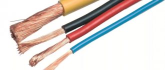
Before connecting Internet sockets, you need to clearly know and understand where and what color to mount each individual twisted pair wire. To do this, you need to know the crimping scheme and the rules for crimping RJ-45 cables yourself.
There are two main types of RJ-45 wire pinouts: straight and crossed. The first type of cable is used to connect end devices (computer/PC, smart TV/Smart TV, switch/Switch) to the so-called router.
The second type of cable is used to connect devices with similar functions (computer - computer, router - router, switch - switch) to each other.
For a direct scheme, the color matches the color in this order: white-orange, orange, white-green, blue, white-blue, green, white-brown, brown. For the cross, everything is the same, but the green ones change places with the orange ones, respectively
First, we leave about 100-150 mm from the plane of the wall along the length of the cable, and cut off the rest of the cable. This length will be sufficient for possible subsequent rewiring of the wiring.
Before starting electrical installation work, you can familiarize yourself with the crimping diagrams for twisted pair cables with 8 and 4 cores, discussed in our other article.
Now you need to free 4 pairs of wires from the outer sheath and from the foil (it acts as protective shielding), if any.
Inside the twisted pair there is also a special thread with which you can easily release all the necessary wiring. You can also use a regular knife or a special cutting surface, which is equipped with almost all crimping pliers.
Crimping pliers will help you easily mount any RJ-45 and RJ-11 connector, the main thing to remember is that if the tool itself does not press the wires enough, then you can press it with a knife or a thin screwdriver
At the next stage, we straighten all twisted pairs of multi-colored wires and carefully “seat” each individual color into its niche according to the color pinout in the socket terminal block.
This must be done in such a way that the rest of the wire with “untouched” insulation falls under the fixing clamp of the terminal block. Now we tighten the fixing bolts with a screwdriver on the terminal block and at the same time press the remaining wires so that they do not come out of their seats.
Finally, with a “feeling of strength,” we recess the clamping connectors on the terminal block with a screwdriver and separately secure each core in the terminal group, while cutting through the braid of small wires. Then we cut off the remains. The wiring must all be located at the same height from the base of the terminal block.
You may also find information about ways to extend twisted pair cables useful.