Installation of electrical wiring in a building (residential or industrial) is carried out in two ways - hidden or open; the electrical wiring itself can be permanent or replaceable. Hidden installation of electrical wiring and its fastening in concrete is considered the most difficult option due to the strength of the building material and the restrictive conditions for laying grooves in panel houses. But even under favorable installation conditions, it will not be possible to install a hidden line in every building. Thus, a wooden house is not intended for such installation, and it is not allowed to lay grooves in a single facing brick, so as not to damage the decorative surfaces of the product - wiring under plaster must be implemented without grooves.
Rules for installing hidden electrical wiring
According to the rules for electrical installations (PUE) and building codes (SNiP), in internal residential premises, power supply lines for household equipment, appliances and devices are laid with copper cable in non-flammable or fire-resistant insulation. Aluminum does not withstand heavy loads, although previously only aluminum internal lines were used.
PUE and SNiP allow the laying of electrical cables of the following sections:
- Supply cable to the switchboard - brand VVG-2, cross-section 6 mm2 or brand VVG-5, cross-section 6 mm2;
- Laying wires around the apartment and connecting electrical sockets - brand VVG-3, cross-section 2.5 mm2;
- The supply to electrical switches and lighting devices is VVG-3 brand, cross-section 1.5 mm2.
Also, when laying an internal electrical network, the best option for connecting electrical outlets is a VVG cable with a cross-section of 2.5 mm2, and for laying lighting networks - a PUGNP wire with a cross-section of 1.5 mm2. For rooms with high humidity, it is recommended to mount PVA grade wire.
The question of when to do wiring before or after plastering is easily resolved - if gating is necessary, then first lay the electrical lines, after which the plaster layer is applied.
Installation of socket boxes
The height of the sockets is not standardized and everyone selects it based on their own preferences; this time all sockets are located at a height of 25 cm from the finished floor (in the center). After marking - crowning.
Ivanov Kostya
The next step is preparing the entrance to the socket boxes and boxes. Over many years of work, I have come to the conclusion that it is better to do this stage “with a reserve.” Hollow out the entrances wider and deeper. Get over your own laziness. Then it will be easier to install the cable. Well, then a hammer drill plus a drill d 20 mm. The depth of the entrances is almost the same as the depth of the socket boxes. The width of the entrances is greater than the width of the “windows” of the socket boxes. The length of the entrances is equal to the diameter of the socket boxes or slightly longer (7-8 cm).
Clarification: the used models of socket boxes are composite and can be mounted in blocks; for single use, the “ears” are removed.
There are several options for installing socket boxes, both before and after plastering. Kostya prefers before plastering.
- Determines the plaster level using a laser plane builder.
- Pulls a thread along the top of the wall.
- Along the laser plane, he places three self-tapping screws around the socket boxes.
Socket boxes and boxes are fixed with gypsum plaster.
- Dusts the niche (brush, vacuum cleaner).
- Coats the edges of the niche.
- Apply a little mixture to the socket/box so that it penetrates into the recesses.
- He presses the socket boxes with a board to the level of the self-tapping screws (the future plaster layer), and recesses the boxes deeper.
TV sockets in the living room (quantity agreed with the customer). The top row will be covered by the TV itself, the bottom row by the cabinet.
Requirements for the number of wire cores
Electrical installation in residential buildings and premises is carried out with a copper cable of three cores. One wire is phase, the second wire is zero, the third wire is grounding.
2 options for grounding wiring have been developed, and they differ from each other in the point of separation of the neutral wire:
- TN-S - separation of the working neutral wire (N);
- TN-CS - separation of the protective neutral conductor (PE).
The grounding wire is designed to protect against electric shock and protect household appliances from failure. When laying wiring, the grounding must have reliable terminal connections. Correct installation of electrical wiring requires that twisting wires together and using bolted connections is strictly prohibited by the PUE and SNiP. In addition to terminals, soldered wiring connections are permitted. A typical installation of electrical wiring in a brick house requires that soldered or terminal connections are hidden in distribution boxes, in glasses for mounting sockets, or in distribution boards with free access.
It is recommended to replace old aluminum wires with copper wiring. If it is not possible to replace aluminum with copper, connecting wiring from different materials is allowed only at terminals.
If you don’t know how to connect wires under plaster, then there is only one answer - waterproof terminals.
Mounting method
When laying without corrugation, the cable is usually secured with ties, or the dowel is secured with clamps containing these same ties.
By securing it in this way, you influence it mechanically in any way. If at first glance nothing seems to happen to it, then over time, this method of fastening can play a cruel joke on you.
Even without using ties, but using special expensive fasteners, you still make the cable sag under its own weight.
Such fasteners negatively affect its insulation. This is not a SIP, which was originally manufactured taking into account sagging under its own weight.
And this, in a few years, will certainly lead to false alarms of the differential protection.
As you can see, all the methods that are presented by installers as simple and fast do not really fit into the definition of “durable installation”.
Installation of hidden electrical wiring: rules and sequence
Wiring is laid in a brick house in stages, and the first step is to develop a layout of the premises and select a connection option. Drawings or sketches of the plan must include a detailed description of the work to be done. For each room, a separate drawing is drawn up with a layout of the walls and a wiring diagram.
Important rules for laying wires:
- A distance of ≥ 150 mm is maintained from the wiring to the floor or ceiling surface, from a window or door ≥ 100 mm, from the heating system pipes ≥ 30 mm;
- Electrical wires are laid strictly vertically or horizontally - tilting at any other angle is strictly prohibited;
- Wiring in a brick house, and even more so in a wooden building, should not intersect; lines overlapping each other is unacceptable.
Induced voltage
Induced voltage is a faithful companion of bundles of wires. It can negatively affect the operation of inexpensive LED lamps, causing backlighting or flickering.
In this case, an inexperienced user will have to call a specialist to deal with a phenomenon that is incomprehensible to him. And for every call you have to pay.
Although, of course, you can try to delve deeply into the problem and figure it out yourself.
Therefore, having saved once on corrugation from one master, get ready to pay others in the future, or spend money on alterations and independent modernization.
Main characteristics of wires
Reliable fastening of the wire to the wall under plaster depends on the properties of the cable or wire. Electric wire under plaster brand and some other distinctive characteristics:
- Section in mm2 –0.75-8.00;
- Material - Cu, Al and their alloys;
- According to the number of cores, wiring under plaster can consist of 1-37 single wires;
- The wiring on the shell before or after plastering can be plastic, rubber or even steel;
- According to the type of insulation, electrical insulation before or after plastering is made from cellulose, plastic, silicone, polymers, rubber.
What is the difference between a cable under plaster and wiring - wires have outer insulation made of thinner and softer material. The retail cost of wire for plaster will be lower than the price for cable. But the cable lasts longer, and this is its main advantage.
The decoding of the brand of wire or cable contains their properties, parameters and quality indicators. The first Cyrillic character means the core material. For example, “A” is a wire or cable made of aluminum (Al). Copper (Cu) wires are not marked. The remaining symbols in the cable or wire brand indicate the parameters and properties of other elements.
High-quality electrical installations, before or after plastering, must consist of two protected layers of insulation. Typical cable laying in the wall of a residential building or in an apartment is carried out in the same way as installing wires.
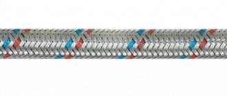
The standard laying of wire in the wall is “PUGNP” brand wire, the cable should be “VVG” brand:
- The symbol “P” denotes a wire whose brand requires plastic insulation. the designation “PP” means flat wire. The symbols “B” and “P” indicate the type of insulation - rubber or polyvinyl chloride;
- A cable of the “VVG” or “NUM” brand, a wire of the “PUNP”, “PVS”, “PUGNP” or “ShVVP” brand is the ideal material option before attaching the wiring to the wall under plaster;
- VVG cable is copper with vinyl insulation. The symbol "G" indicates an unarmored cable type. The VVG brand has several versions of the same cable, but the parameters will be slightly different. Thus, the “VVG NG” brand is a non-flammable product, the “VVG Z” brand is additionally protected from the outside;
- “NUM” is a cable with a round cross-section and an increased degree of strength. It is mainly used for organizing hidden wiring, as it has poor resistance to sunlight.
- “PVS” is a connecting wire covered with vinyl insulation. Suitable for any type of work.
- “PBPP” is a flat wire in polyethylene. Designed for cable channel for plastering lighting lines;
- The “PBGPP” brand is similar to “PBPP”, and is distinguished by a multi-core flexible wire;
- “ShVPP” is a copper wire, flat, with increased flexibility.
Wiring under the floor
Installing electrical wiring under the floor is an ideal way to create hidden cabling without resorting to horizontal grooves in the walls. In this case, the cable (main wire) is supplied directly to the locations of sockets, switches and distribution boxes.
The method of creating floor wiring directly depends on what material the floors are planned to be made from. In general, it is necessary to focus on the rules of the PUE that are already known to us.
sergey_savFORUMHOUSE Member
In the voids of building structures - read SP31-110-2003 clause 14.15 or similar - PUE 7 clause 7.1.38. That is, if something in the structure turns out to be flammable (joists, for example), then the direct path is to metal blind boxes and pipes.
If the wiring is installed in the lower layers of the cement floor, then a simple protective corrugation is sufficient for its installation. Of course, it is possible to lay a cable inside the screed without any corrugation at all, but in this case it will not be possible to replace the wiring without resorting to destroying the floor covering. By the way, the difficulty of repairing and replacing cables (wires) is the only significant drawback of floor wiring, and it should definitely be taken into account when deciding on the type of electrical wiring.
So, we have introduced you to the main methods of installing internal electrical wiring, which depend on the characteristics of the building materials in the room. You can read in more detail about the experience of laying cables on various building structures in the corresponding section of our portal. You can learn about additional features of installing wiring on walls, floors and ceilings from the corresponding video. And the article about protecting consumer electronics from sudden voltage surges will be of interest to anyone who does not want to one day face the unpleasant consequences of such a problem.
Selection of wire cross-section
An incorrect choice of wiring cross-section can lead not only to an overload in the general network, but also to a fire in the local overload area, which often means overheating of the wiring. The tables in this section will help you correctly determine the cross-section and select the type of wiring depending on the loads and characteristics of the wires.
| Number of cores and cross-section | Class | ⌀ with insulation in mm | ⌀ with shell in mm | Ωmin (Ohm) with a wire length of 1.0 km and t = 20°C | Coil length in meters | Wire weight (kg/km) | Dmin bending in mm |
| 3 x 4 | I | 3.73 | 11.62 | 4.61 | 100.0 | 235.19 | 7,5 |
| 3 x 6 | I | 4.22 | 12.67 | 3.08 | 100.0 | 305.92 | 7,5 |
| 3 x 10 | I | 5.46 | 15.34 | 1.83 | bar | 475.30 | 7,5 |
| 3 x 16 | II | 7.02 | 18.69 | 1.15 | bar | 724.59 | 7,5 |
| 4 x 1.5 | I | 2.67 | 10.03 | 12.1 | 100.0 | 153.33 | 7,5 |
| 4 x 2.5 | I | 3.05 | 10.95 | 7.41 | 100.0 | 201.75 | 7,5 |
| 4 x 4 | I | 3.73 | 12.59 | 4.61 | 100.0 | 285.59 | 7,5 |
| 4 x 6 | I | 4.22 | 13.77 | 3.08 | 100.0 | 375.54 | 7,5 |
| 4 x 10 | I | 5.46 | 16.76 | 1.83 | bar | 588.92 | 7,5 |
| 4 x 16 | II | 7.02 | 20.52 | 1.15 | bar | 902.80 | 7,5 |
| 5 x 1.5 | I | 2.67 | 10.81 | 12.1 | 100.0 | 178.58 | 7,5 |
| 5 x 2.5 | I | 3.05 | 11.84 | 7.41 | 100.0 | 237.36 | 7,5 |
| 5 x 4 | I | 3.73 | 13.67 | 4.61 | 100.0 | 338.80 | 7,5 |
| 5 x 6 | I | 4.22 | 14.99 | 3.08 | 100.0 | 448.59 | 7,5 |
| 5 x 10 | I | 5.46 | 18.34 | 1.83 | bar | 707.92 | 7,5 |
| 4 x 16 | II | 7.02 | 22.55 | 1.15 | bar | 1089.41 | 7,5 |
Using the data in the table, you can quickly calculate the wiring cross-section in mm2, based on the maximum load current values:
| Open laying scheme | Section in mm | Closed routing scheme | ||||||||||
| Cu | Al | Cu | Al | |||||||||
| I (A) | P (kW) | I (A) | P (kW) | I (A) | P (kW) | I (A) | P (kW) | |||||
| 220 V | 380 V | 220 V | 380 V | 220 V | 380 V | 220 V | 380 V | |||||
| 11 | 2.4 | — | — | — | — | 0.5 | — | — | — | — | — | — |
| 15 | — | — | — | — | 0.75 | — | — | — | — | — | — | |
| 17 | 3.7 | 6.4 | — | — | — | 1.0 | 14 | 3.0 | 5.3 | — | — | — |
| 23 | 5.0 | 8.7 | — | — | — | 1.5 | 15 | z.z | 5.7 | — | — | — |
| 26 | 5.7 | 9.8 | 21 | 4.6 | 7.9 | 2.0 | 19 | 4.1 | 7.2 | 14 | 3.0 | 5.3 |
| 30 | 6.6 | 11 | 24 | 5.2 | 9.1 | 2.5 | 21 | 4.6 | 7.9 | 16 | 3.5 | 6.0 |
| 41 | 9.0 | 15 | 32 | 7.0 | 12 | 4.0 | 27 | 5.9 | 10 | 21 | 4.6 | 7.9 |
| 50 | 11 | 19 | 39 | 8.5 | 14 | 6.0 | 34 | 7.4 | 12 | 26 | 5.7 | 9.8 |
| 80 | 17 | 30 | 60 | 13 | 22 | 10 | 50 | 11 | 19 | 38 | 8.3 | 14 |
| 100 | 22 | 38 | 75 | 16 | 28 | 16 | 80 | 17 | 30 | 55 | 12 | 20 |
| 140 | 30 | 53 | 105 | 23 | 39 | 25 | 100 | 22 | 38 | 65 | 14 | 24 |
| 170 | 37 | 64 | 130 | 28 | 49 | 35 | 135 | 29 | 51 | 75 | 16 | 28 |
Types of terminations
The connection can be boxed or daisy-chained:
- The box type connection has a simple solution - the cable runs through all the rooms of the apartment, and in each individual room, through a junction box (junction box), wires for electricity distribution points, switches and lighting fixtures are routed from the cable. When implementing this connection option, the cost of purchasing wiring is minimal, and this is the main advantage of the method. The disadvantage of this scheme is that there is no physical possibility to control individual local sections of the internal electrical network from an external switchboard;
- Daisy chain wiring is a more modern option, which is why it is often called European. The essence of the scheme is that two cables are supplied from the external switchboard to each individual room: one for connecting lighting devices, the second for distribution points. Each cable is insured by connection through an RCD installed in the panel. The wire consumption when disconnecting with a loop is greater than in the first option, but much safer. Also, daisy chain connection allows for control and monitoring of the internal electrical network.
The importance of applying standards
Compliance with electrical wiring standards in the apartment is achieved by strictly complying with the requirements of legislative acts.
The importance of their use is as follows:
- selection of conductors whose cross-section corresponds to the power of consumers;
- eliminating the risk of electric shock to people;
- optimal location and correct selection of the required number of sockets;
- preventing the risk of fire in the network;
- preventing breakdowns of household appliances.
If you strictly follow SNiPs for electrical installation, you can correctly calculate the need and type of conductors, which helps reduce construction costs.
Line layout diagrams
The principle of wiring power lines is simple - the higher the load, the thicker the wire or cable should be. At the entrance to the apartment, the cable must have the largest cross-section, since the entire apartment load falls on it. For branches to distribution points and lighting, a wire of a smaller cross-section is used.
Based on these requirements, three electrical wiring options were developed:
- Daisy chain circuit (bus connection). This is the laying of a common power line with a large cross-section cable, from which branches are laid through distribution boxes to consumers;
- The radial scheme is considered more reliable. It is implemented as a supply of separate wires from the distribution board to each point of distribution or consumption. The disadvantage of the scheme is the high consumption of wire or cable;
- The last scheme is a combined one, assembled on the basis of a loop and a radial one.
In new buildings, combined wiring is used, in houses of old construction - the first two variants of circuits.
Important! You cannot hide electrical wiring in the joints and seams of walls - PUE Chapter 7.1.
Features of working with the input cable
The installation of wiring in the house, on the example of which the educational program was organized, began with the input cable - it has already been brought into the room where the shield will be located, and it can be used. The rough screed has not yet been filled in and the cable simply comes out of the ground, which greatly simplifies the further process. Kostya warns that it is a mistake to pour a rough screed until the cable is connected to the wall, otherwise you will have to chisel the concrete, since strong bending is not recommended. Therefore, either the screed is poured after, or when pouring, an area is left near the cable and the wall.
Ivanov Kostya
Let's continue. There is a house, there is an input cable - we need to work. First of all, we will provide ourselves with electricity. The days are short now and lighting is indispensable. If you don’t have a DIN rail at hand, you can hang the machines directly from the cable. It is enough to attach the cable itself to the wall. The extension plug fits perfectly into the terminals of the two-pole circuit breaker. In this case, I have two single-pole ones. The extension cord itself is placed on the window, and the temporary lighting wire rises from it to the ceiling. When I leave the site, I simply turn off the machine.
The cable to the wall will pass in a layer of sand filling, and to the shield - in a fine.
Installation of hidden electrical wiring in walls
Hidden electrical wiring is installed following the following steps:
- The line for laying the electrical route is marked and the tracing is done. At this stage, you can use existing voids in the walls;
- Next, the walls are grooved according to the markings, niches are made in the walls for installing electrical sockets;
- The room is put in order;
- In places where electrical outlets are installed, mounting boxes (plastic cups for outlets) are attached. Installation areas for mounting switches are also equipped;
- The wire is inserted into the socket boxes; for the socket blocks, not a wire, but a cable is used. The length of the free ends of the wire according to the requirements of SNiP ≥ 150 mm.
Electrical wiring and cables for low-current circuits (communication lines, TV cable, surveillance systems) are supplied through separate grooves; it is allowed to lay them parallel to power lines. The cable channel should be laid without twisting the wires.
Before attaching wiring to electricity distribution points, it is necessary to secure all wiring with alabaster or plaster in grooves. The channels are leveled from above with plaster. Small cross grooves can be connected to each other with plaster immediately after laying the power lines.
If the electrical wiring diagram provides for the installation of junction boxes, then the wires. Which went into the box should first be unsoldered, all connections checked for contact and strength, the junction boxes themselves should be tightly and firmly closed.
The wire is passed into corrugated (cemented) pipes after all surfaces are plastered and puttied.
Installation of electrical sockets and switches is carried out only after completion of final repair work.
Marking
Before gating, make markings.
You need to think about gating and fixing the wiring before finishing the room, before wallpaper is glued, linoleum is laid and furniture is installed.
Marking should be done on a bare wall.
At the selected location, the area through which the cables will be laid is marked.
Marking can be done using a pencil and ruler.
Keep in mind that you will need to decide in advance on the location of sockets and switches. The holes for their installation will need to be made at the same time as the groove for securing the wiring. The width of the groove is determined based on the number and cross-section of the wire that will be placed in it.
Wall cutting and wire laying
You can make grooves in the walls using simple hand tools - a hammer and a chisel - but it is much faster and easier to use a hammer drill or grinder.
Working with a grinder:
Two parallel recesses are cut in the wall along the wire laying line, and the insides are knocked out with a hammer drill with a flat lance. The groove is made in width depending on the thickness of the wire or cable run. The depth of the groove should be such that all wires can be plastered. The grinder is used when you need to make grooves in concrete walls.
Working with a hammer drill:
It is easier to punch brick walls directly with a hammer drill. Without using a grinder. Brick walls are much softer and the work will go much faster. There will also be much less dust.
The wire is laid in the recesses so that at least 5 mm remains to the outer surface. This will be the layer of plaster that will cover the groove.
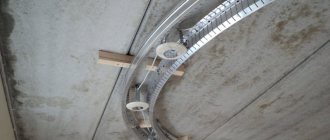
Installation of wires in corrugated pipes
There is a special mechanism for pulling wires through the pipe. At home, you can use a cable of suitable diameter. According to SNiP, 30% of the pipe volume should remain free.
It is strictly forbidden to string low-current wires and power cables through the same pipe. It is allowed to lay lines parallel to each other. But without intersections, twisting and overlaps.
The angle of rotation of the corrugated pipe must be less than 90˚, otherwise difficulties will arise with pulling the cable.
Compliance with standards
Safe connection of wires
When carrying out electrical work in residential premises, it is necessary to comply with the standards established for them regarding the following parameters:
- Section of veins. You need to select conductors with a calculation of the maximum load that will affect them. If the permissible power is exceeded, the metal heats up, which leads to the formation of smoke, melting of the insulation and the risk of fire.
- Laying lines. Network fragments can only be located in the vertical and horizontal directions; they should not intersect each other during internal installation. Groups of sockets should be located at the same distance from the floor.
- Switching. The main rule is the prohibition on directly connecting copper and aluminum conductors. To do this, you need to use an indirect connection in a bolt and nut, tires or spring terminals. Wires made of the same metal can be twisted and then insulated.
- Location. The slightest possibility of mechanical damage, melting of wiring elements and water getting into them must be excluded.
Compliance with standards is the basis for the safety and durability of the structure.
Installation of hidden electrical wiring behind wall panels
Wall thermal panels are not uncommon in modern housing construction. How to lay wires under them so as not to damage the surface? It is recommended to distribute the main wiring diagram under the panels in advance. The process is similar to laying cables in walls, but without gating.
Follow these recommendations from professional builders:
- Pipes are made of non-combustible materials;
- For powerful electrical appliances, special mounting boxes are used;
- It is strictly forbidden to lay wires or cables across them.
Wall thermal insulation panels are mounted on a metal profile. Holes for laying the cable are pre-drilled in the profile. Perforated metal profiles are also sold. Corrugated pipes are used to pull wires - without such protection, the wiring insulation can be damaged by the sharp edges of the profile.