Properties of plasma spraying
When working with metal structures, sometimes it is necessary to supplement them with additional properties so that they can be used in any field.
This way the surface will become even more resistant to moisture, high temperature and chemicals.
Diffuse metallization has many features that make it unique among other types of metal processing.
- Due to exposure to high temperatures (five to six thousand degrees), the surface treatment procedure is greatly accelerated. The process itself takes place in a fraction of seconds, and the result is excellent.
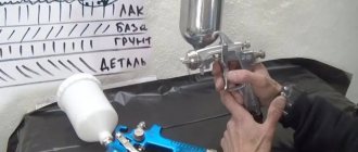
- The result is a combined ball. You can apply not only metal elements, but also gas particles from a plasma jet. Thus, the metal surface is coated with atoms of certain metal elements.
- If you carry out classical metal spraying, then the application occurs unevenly, takes a very long time and involves oxidative processes. But with the help of hot plasma, the correct temperature and pressure are obtained, due to which a high-quality coating is formed.
- The plasma jet transports particles of metal and gases at the speed of light, so you won’t even understand anything. Thus, welding occurs with powders, rods, rods and wires. Afterwards, a layer of several microns to one millimeter is formed on the base of the structure.
“To carry out diffuse metallization, complex equipment is used, in contrast to gas-plasma equipment. To carry out plasma metallization, you need to use gas and electric devices.”
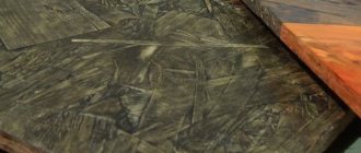
Rice. 3. Micrograph of plasma coating.
Plasma spraying is one of the methods of gas-thermal coating. This process is based on heating the sprayed material to a liquid or plastic state, transferring it to the substrate with a high-temperature plasma jet, followed by the formation of a coating layer.
In plasma spraying, powders, wires, and rods are used as spraying materials. Powder spraying is the most widely used. The scheme of plasma spraying using powder materials is shown in Fig. 1. In a plasma torch consisting of a water-cooled cathode assembly (cathode 2 and housing 3) and an anode assembly, a plasma arc 8 is excited using a constant welding current source 9, which is stabilized by the walls of the nozzle channel and the plasma-forming gas entering through inlet 1. The powder is supplied from powder feeder 6 with the help of gas supplied through inlet 7.
The temperature of the plasma jet reaches 5000-55000 °C, and the outflow speed is 1000-3000 m/s. In the plasma jet, the powder particles melt and acquire a speed of 50-500 m/s. The flight speed of powder particles depends on their size, the density of the material, the strength of the welding arc current, the nature and flow rate of the plasma-forming gas, and the design of the plasma torch. The powder is introduced into the plasma jet below the nozzle exit, at the nozzle exit, or directly into the nozzle. Heating of sprayed parts does not exceed 100-200 °C.
Rice. 1. Scheme of plasma powder spraying:
1 — supply of plasma-forming gas; 2 — plasmatron cathode; 3 — cathode body; 4 - insulator; 5 - anode body; 6 - powder feeder; 7 — gas supply transporting the powder; 8 — plasma arc; 9 - power supply.
The advantages of the plasma spraying method include the possibility of obtaining coatings from most materials that melt without decomposition and restrictions on the melting temperature. The productivity of plasma spraying is quite high: 3-20 kg/h for plasma torches with a power of 30-40 kW and 50-80 kg/h for plasma torches with a power of 150-200 kW.
Plasma spraying is used to apply coatings to both flat surfaces and bodies of rotation and curved surfaces. The coating is characterized by a layered structure with high heterogeneity of physical and mechanical properties (Fig. 2). The type of bonds between the coating and the part (substrate), as well as between the coating particles, is usually mixed - mechanical adhesion, the force of physical and chemical interactions. The adhesion strength of the coating to the substrate is usually 10-50 MPa when tested for normal peeling.
The physical features of the formation of coatings determine the appearance of open and closed porosities. As the thickness of the applied layer increases, the open pores close and the porosity of the coating decreases. Therefore, the density of plasma coatings differs from the density of the material and ranges from 80-97%. Typically, the porosity of plasma coatings is 10-15%.
The thickness of the coating is practically unlimited by the capabilities of the method itself. However, due to the physical characteristics of the coating formation process, as the thickness of the applied layer increases, internal stresses in it increase, which tend to tear the coating away from the substrate. Therefore, usually the coating thickness does not exceed 1 mm. The structural load is carried by the material of the part, and the coating material imparts properties to the surface of the part such as hardness, wear resistance, etc.
Argon, high-purity nitrogen, hydrogen, helium, as well as mixtures of these and other gases are used as plasma-forming gases. In recent decades, plasma spraying processes using a mixture of air and flammable hydrocarbon gas (methane, propane-butane) as a plasma-forming gas have been successfully developed.
Rice. 2. Diagram of the structure of the plasma coating:
1 - boundary between particles of sprayed material;
2 - boundary between layers;
3 - boundary between the coating and the part;
4 - particle of sprayed material;
5 - surface of the part.
Various plasma torches are used to generate plasma. The range and level of specific powers implemented in a specific design characterize the efficiency of converting the electrical energy of the arc into thermal plasma jets, as well as the technological capabilities of the plasma torch.
The task of developing a technological plasma torch always comes down to the creation of a relatively simple, repairable design that ensures stable long-term operation in a wide range of changes in the welding arc current, flow rate and composition of the plasma gas, as well as generating a plasma jet with reproducible parameters, which makes it possible to effectively process materials with different properties.
In spraying practice, both homogeneous powders of various materials (metals, alloys, oxides, oxygen-free refractory compounds) and composite powders, as well as mechanical mixtures of these materials, are used.
The most common powder materials are:
metals - Ni, Al, Mo, Ti, Cr, Cu;
alloys - alloy steel, cast iron, nickel, copper, cobalt, titanium, including self-fluxing alloys (Ni-Cr-B-Si, Ni-B-Si, Co-Ni-Cr-B-Si, Ni-Cu-B- Si);
oxides of Al, Ti, Cr, Zr and other metals and their compositions;
oxygen-free refractory compounds and hard alloys - carbides of Cr, Ti, W, etc. and their compositions with Co and Ni;
composite clad powders - Ni-graphite, Ni-Al, etc.;
composite conglomerated powders—Ni-Al, NiCrBSi-Al, etc.;
mechanical mixtures - Cr3C2+NiCr, NiCrBSi+Cr3C2, etc.
In the case of using composite powders in thermal spray technology, the following goals are pursued:
use of the exothermic effect of interaction of components (Ni-Al, Ni-Ti, etc.);
uniform distribution of components in the coating volume, for example, such as cermets (Ni-Al203, etc.);
protection of the particle core material from oxidation or decomposition during spraying (Co-WC, Ni-TiC, etc.):
formation of a coating with the participation of a material that does not independently form a coating during gas-thermal spraying (Ni-graphite, etc.);
improving the conditions for coating formation by increasing the average particle density, introducing components with high enthalpy.
Powders used for spraying should not decompose or sublime during the spraying process, but must have a sufficient difference between the melting and boiling points (at least 200 ° C).
When choosing powder materials for obtaining various plasma coatings, the following points must be taken into account.
The particle size distribution of the powder materials used is of paramount importance, since the productivity and utilization rate, as well as the properties of the coatings, depend on it. The particle size of the powder is selected depending on the characteristics of the thermal energy source, the thermophysical properties of the sprayed material and its density.
Usually, when spraying a fine powder, a more dense coating is obtained, although it contains a large amount of oxides resulting from heating of the particles and their interaction with the high-temperature plasma flow. Excessively large particles do not have time to warm up, so they do not form a sufficiently strong bond with the surface and with each other, or simply bounce off upon impact. When spraying a powder consisting of a mixture of particles of different diameters, smaller particles melt in the immediate vicinity of the point where they are fed into the nozzle, melt the hole and form nodules, which from time to time break off and fall in the form of large drops onto the sprayed coating, deteriorating its quality. Therefore, spraying should preferably be carried out with powders of one fraction, and all powders should be subjected to dispersion (classification) before spraying.
For ceramic materials, the optimal powder particle size is 50-70 microns, and for metals - about 100 microns. Powders intended for spraying must have a spherical shape. They have good flowability, which facilitates their transportation to the plasma torch.
Almost all powders are hygroscopic and can oxidize, so they are stored in closed containers. Powders that have been in an open container for some time are calcined in a stainless steel drying oven with a layer of 5-10 mm at a temperature of 120-130 °C for 1.5-2 hours before spraying.
The powder for spraying is selected taking into account the operating conditions of the parts being sprayed.
Possible defects of the plasma-arc coating method are peeling of the sprayed layer, cracking of the coating, the appearance of large drops of the coating material, drops of copper on the surface, as well as variations in the thickness of the coating (above the permissible).
In order to increase the adhesive and cohesive strengths and other quality characteristics, plasma coatings are subjected to additional processing in various ways: rolling in rollers under current, cleaning the sprayed surfaces from scale and removing particles weakly adhered to the base or to the previous layer with metal brushes during the spraying process, jet-abrasive and ultrasonic treatment, etc.
One of the most common ways to improve the quality of coatings made of self-fluxing alloys is their reflow. For melting, induction or furnace heating, heating in molten salts or metals, plasma, gas flame, laser, etc. are used. In most cases, preference is given to heating in inductors with high frequency currents (HF). Sprayed coatings of the Ni-Cr-B-Si-C system are subjected to melting at 920-1200 0C in order to reduce the initial porosity, increase hardness and adhesion strength to the base metal.
The technological process of plasma spraying consists of preliminary cleaning (by any known method), activation treatment (for example, abrasive jet) and direct coating by moving the product relative to the plasmatron or vice versa.
Literature:
Lashchenko G.I. Plasma hardening and sputtering. – K.: “Ecotechnology”, 2003 – 64 p.
You may also be interested in:
- Electroplating
- Plasma hardening
- Supersonic spraying
- Cold gas dynamic spraying
- Anodizing of metals
What equipment is used for diffuse spraying?
To perform sputtering with metal ions, high-temperature technical plasma is used - a combination of many quantum particles of light, positive ions, neutral elements, and electron gas.
Due to the high temperature, electrical gas discharges create strong thermal ionization of elements that are connected to each other and the external environment. Therefore, there is a simple plasma, weakly, moderately and strongly ionized (in turn divided into low-temperature and high-temperature).
In order to perform plasma ionization of metal structures, specific equipment is used - plasma equipment.
As a rule, an arc, pulse or spark electric discharge is used.
To implement all this, you need to use:
- High-frequency generator (or welding modifier) to create a discharge.
- A sealed chamber (it contains elements for treating the base with diffusion spraying).
- Gas container. Under the influence of electric discharge, ionization of elements occurs.
- A gas pressure device (vacuum or pump equipment is suitable).
- A system for changing current, pressure, voltage and increasing or decreasing the thickness of the metal surface.
The order of plasma ionization occurs in the following order:
- Fixing the part in a sealed chamber and generating an electrical discharge.
- The working atmosphere is pumped up with pressure and powder particles (a high-temperature plasma is obtained that transfers powder elements to the base of the workpiece).
- With vacuum spraying, in conditions of inert gas or low pressure, it is possible to accelerate the movement of elements, resulting in a more dense coating with good adhesion.
Ultrasonic pressure treatment and ultrasonic hardening
The main technological parameters of ultrasonic hardening (USH) are the duration of exposure (t), ball diameter (dsh) or rounding radius of the working part of the tool (r), vibration amplitude (Ak), effective mass of the tool (Gin), longitudinal feed (s), number passes (i), the speed of movement of the part being hardened (v), the initial surface roughness (Ra) and the quality of the surface layer.
To improve the physical and mechanical properties of parts, finishing and strengthening treatment by surface plastic deformation (with a spherical or cylindrical tip) is used. In this case, the metal of the asperity protrusions moves in both directions from the point of contact with the deforming element. The height of the irregularities decreases, forming a new microrelief. To obtain the required surface roughness, it is necessary to apply the minimum necessary force to the deforming element, sufficient for plastic deformation to occur.
When rolling and rolling with roller and ball heads, mandrating, and pulling with smoothing broaches, the shape of non-rigid parts and parts of variable rigidity may be distorted. The application of ultrasonic vibrations (UV) to the deforming tool reduces the magnitude of the static load during plastic deformation of metals.
The installation diagram of the ultrasonic device (Fig. 1) includes an ultrasonic generator, a magnetostrictive transducer 5, a waveguide 3 and a deforming tip 2. The acoustic system is mounted in a movable housing 4, which can move along the axis of the fixed housing. The installation and regulation of the required radial force is carried out using a calibrated spring 7 and a screw 8. The tip 2 performs ultrasonic testing and with a small force P is pressed against the workpiece 1.
Rice. 1. Scheme of ultrasonic hardening with a spring-loaded ball or diamond tip
In practice, steel or carbide balls can be used as a tool, loosely or rigidly connected to the waveguide of the transducer, and in diamond burnishing, polished diamond crystals are used, sealed in steel holders. The radius of curvature of the working part of the diamond tip is 1. . . 4 mm and depends on the processing conditions, the material of the processed surface and the rigidity of the technological system. It has been established that under the influence of ultrasonic sound with an amplitude Ak = 10 μm, the rate of deformation of the surface layers increases 100 times and is accompanied by hardening. Serial equipment is used as equipment for performing ultrasonic hardening. The ultrasonic emitter is fixed in the tool holder (Fig. 2).
Areas of application of diffusion metallization
Due to the fact that any metal or metal alloy can be subject to plasma spraying, this type of diffusion treatment is used on an industrial scale, as well as for restoration work.
The powdered metal is transferred to plasma equipment, where the high temperature plasma melts it and absorbs it into a thin ball of metal.
Next, let's look at where spraying is used:
- production of aircraft, space and rocket launchers;
- mechanical engineering and energy;
- metallurgy and chemical production;
- oil production, oil refining and coal mining industries;
- in the field of transport and equipment production;
- in the field of restoration of machines, installations and obsolete elements.
After the plasma-powder jet passes through the electric arc and settles on the base, it is enriched with the following properties:
- resistance to elevated temperatures;
- corrosion resistance;
- electrical insulation;
- thermal insulation;
- resistance to erosion;
- cavitation protection;
- magnetic attraction;
- semiconductivity.
“Plasma powders are filled using plasma-forming or transported gas. Due to metallization, various coatings are obtained, regardless of the melting point (metal, combined alloy, carbide, oxide, boride, nitride, composite). After processing, the material will not suffer one bit in appearance, but rather will be enriched with additional properties. Hard and soft balls, refractory materials, and media of any density are subject to spraying.”
Advantages of axial powder input
Axial powder injection is a quantum leap in plasma spraying technology. The point here is not only that with axial input, powder losses are significantly reduced, but also that the possibility of spraying completely different powder materials that are unsuitable for radial input opens up. Since this aspect is fundamentally important for understanding the following sections, we will dwell on it in more detail.
So, what happens when powder is radially introduced into the flame jet at the nozzle exit? We list the disadvantages of such input:
- Only very narrow fraction powders are suitable for radial injection, for which it is necessary to precisely select the pressure of the carrier gas. What does this mean?: If the carrier gas pressure is insufficient, the powder particles will “bounce” off the flame jet; if the carrier gas pressure is too high, they will “shoot through” this flame; if the powder consists of particles of different sizes, then it is in principle impossible to select the “correct” pressure of the carrier gas: the smallest particles will always “bounce off”, and the largest ones will always “shoot through”, that is, neither of these particles will be in the sprayed coating there won’t be, but only some “average” particles. Fine-grained powders are especially difficult to introduce due to their increased dispersion by the carrier gas (a typical dust cloud around a torch).
- When introducing radial powder, it is impossible to use in the powder mixture not only particles of different sizes, but also different densities (different masses) for the same reason: heavier particles fly through the flame more easily than lighter ones. Thus, attempting to use complex powder mixtures will result in a distortion of the coating composition compared to the composition of the powder mixture.
- An increase in the velocity of plasma-forming gases complicates the radial injection of powder, since the ranges of required carrier gas pressures and particle size distributions are further narrowed. In practice, this means the following: the higher the flame speed, the lower the spraying efficiency during radial powder injection. It is impossible under any circumstances to introduce all the powder into the flame without loss.
- The location of the powder nozzles next to the hot flame zone causes their heating, which is compensated only by cooling by the gas carrying the powder. If the speed of the cooling gas is not enough for cooling, then powder particles can stick to the edges of the nozzle opening, forming sagging. The stuck pieces periodically come off the nozzle, fall into the flame and cause a characteristic defect - “spitting”, leading to the formation of coarse porous inclusions in the coating. Since the flow rate of the carrier gas is strictly related to the flame parameters (see point 1), a problem arises: for some powders there are simply no parameters that eliminate the “spitting” effect, especially if these powders are low-melting and/or fine-grained.
Switching to axial injection of powder allows you to completely get rid of the above problems:
- Carrier gas pressure and velocity are no longer tied to flame and powder parameters. The only condition is that the pressure of the carrier gas must be slightly higher than the pressure of the plasma-forming gas in the nozzle at the point where the powder is introduced. Due to the axial input, any powder is completely captured by the flame.
- It is always possible to select a pressure of the carrier gas at which “spitting” associated with powder sticking to the edge of the hole in the powder nozzle will not occur.
- It is possible to use powder mixtures of any complexity and fractional composition. Particles of different sizes will acquire different speeds and temperatures, but all will eventually take part in the formation of the coating. The fact that small particles become significantly hotter than large ones when axially introduced into a plasma flame opens up new possibilities for the design of powder mixtures. The main part of this book is devoted to the creation of such polyfractional compositions.
The author was very fortunate to have had an Axial III plasmatron with axial powder injection at his disposal for many years. If not for this, the creation of new multicomponent coatings would simply be impossible.
Wires and cord materials
Continuous electrodes in the form of wires of various designs are used primarily for metallization of surfaces. Spraying the metal of a continuous electrode requires its mandatory melting and transition into a liquid state. When metallizing, wire materials with a diameter of 0.5-5.0 mm are used, which are divided into the following groups: 1) solid wire; 2) flux-cored wires with a metal sheath; 3) flux-cored wires with an organic sheath.
Solid wires, usually from pure metals or alloys based on them, are produced by drawing methods. This type of wire materials is most widely used in metallization. Wire preparation before spraying most often involves degreasing and etching. Organic contaminants are removed by degreasing; etching - oxide films. The compositions of the baths and processing modes are determined by the brand of wire. In many cases, wire abrasive blasting, electropolishing and other processing methods are effective.
Of the iron-based wires, carbon and low- and medium-alloy wires are most widely used for metallization. Carbon and low-alloy steels are most appropriately used for restoration repairs by flame spraying or electric arc metallization. Sprayed coatings have a fairly high hardness. Refurbished products are as worn as the original ones. For spraying, wire made from St3 steels is mainly used; U 7; 40X; 50HFA, etc. When spraying coatings from steel U 7, the microhardness of the metal fluctuates between 2100-7750 MPa. High-carbon steels and cast irons, when sprayed, form brittle coatings that are practically unsuitable for use.
Flux-cored wires with a metal sheath are promising for spraying composite coatings. Flux-cored wires are produced by rolling a strip into a tube with simultaneous filling of dispersed charge into the resulting cavity. With subsequent drawing of the filled tube, wire of various diameters is obtained. In this case, the ratio between the mass of the powder and the shell is easily adjusted. Various combinations are possible in the arrangement of the shell and powder (Fig. 3.30).
Cord materials are flux-cored wires with an organic shell, which are used mainly for flame spraying and less often for plasma spraying.
Rice. 3.30. Flux-cored wires (I-III) and cord materials with an organic sheath (IV).
The preparation of flux-cored wires before spraying is carried out by degreasing them by wiping them with strong solvents (gasoline, acetone, etc.) or by abrasive blasting.
Rods and tubular electrodes
Solid cross-section rods are made by casting. Powder rods are formed from crushed materials such as oxides and then sintered. Typically their diameter is 3-6 mm and length 500-600 mm.
Rolling and rolling out surfaces
Similar to ultrasonic hardening treatment, the same equipment is used to perform finishing and hardening treatment of the external surfaces of parts by rolling, and the internal surfaces by rolling.
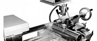
Rice. 2. Ultrasonic hardening of the shaft surface on a 16K20 screw-cutting lathe
Depending on the material of the part, the pressure on the roller is 5. . . 20 MN/m2 with a number of passes up to 4. Rolling provides a roughness of the treated surface Ra = 0.4. . . 0.05 µm. The rolling tool shown in Fig. 3, installed in the tool holder with shank 7.
Rice. 3. Hardening treatment of the outer surfaces of parts by rolling
Rolling of the surface to be treated is carried out by ball 2, which rests against the outer race of bearing 10, mounted on axis 9, and is kept from falling out by cap 8. Under the influence of rolling force, ball 2 is pressed out and moves quill 3 in the bore of housing 4, which compresses spring 5. With the help of Screw 6 adjusts the compression force of the spring. For rolling processing, the tool holder of a lathe with a rolling tool is brought until the ball comes into contact with the surface of the pre-processed part. Then, using the caliper transverse feed screw along the dial, a preload of 0.5 is created. . . 0.8 mm. Set the spindle speed to 1200...1500 min-1 and longitudinal feed 5 = 0.3. . .1.5 mm/rev. , turn on the machine and make 2-3 longitudinal passes to the right and left°. Spindle oil is used as a cutting fluid.
Balls and rollers for rolling (rolling) are made of hardened steel or hard alloy
List of used literature
1. Borisov Yu.S. Gas thermal coatings from powder materials / Yu.S. Borisov, Yu.A. Kharlamov. – Kyiv: Naukova Dumka, 1987. – 210 p. 2. Vityaz P.A. Theory and practice of flame spraying / P.A. Vityaz, V.S. Ivashko, E.D. Manuilo. – Minsk: Science and technology, 1993. – 295 p. 3. Kudinov V.V. Plasma application of refractory coatings / V.V. Kudinov, V.M. Ivanov. – M.: Mechanical Engineering, 1981. – 192 p. 4. Rykalin N.N. Physical and chemical problems of joining dissimilar materials / N.N. Rykalin, M.X. Shorshorov, Yu.L. Krasulin. // Inorg. materials. – 1965. – T.1. – P. 29 – 36. 5. Terekhov D.Yu. Method of surface preparation before thermal spraying / D.Yu. Terekhov, B.M. Soloviev // Copyright certificate of the USSR No. 1638198 AI С23С 4/02 08/30/91 Bull. No. 32. – All-Union Scientific and Production Association for the Restoration of Parts “Remdetal”. 6. Nadolsky V.O. Method for preparing the surface of parts / V.O. Nadolsky, A.N. Navoznov // Copyright certificate of the USSR No. 1758082 AI S23S 4/02 08/30/92. Bull. No. 32. 7. Medvedev Yu.A. On the influence of roughness and the degree of hardening on the adhesion strength of plasma coatings / Yu.A. Medvedev, I.A. Morozov // Physics and chemistry of materials processing. – 1975. – No. 4. – pp. 27-30. 8. Popovkin B.A. Progressive technology and equipment for shot blasting metal / B.A. Popovkin // Technology, organization of production and management. – 1978. – No. 10. – pp. 31-35. 9. Ivashko V.S. Adhesion strength of coatings made of self-fluxing hard alloys / V.S. Ivashko // Mechanical Engineering. – 1979. – Issue. 2. – pp. 103-105. 10. Kudinov V.V. Production of coatings by high-temperature spraying / V.V. Kudinov., L.K. Druzhinin. – M.: MIR, 1973. – 85 p. 11. Kupriyanov I. L. Gas-thermal coatings with increased adhesion strength / I. L. Kupriyanov, M. A. Geller. – Minsk: Science and technology, 1990. – 176 p. 12. Masino M.A. Organization of restoration of automobile parts / M.A. Masino. – M.: Transport, 1981. – 176 p.
The main factors influencing the formation of a particle coating during thermal spraying
To begin with, we will simply list all the main factors that, according to the results of practical experience, influence the formation of coatings. We will divide these factors into five large independent groups (within individual groups, parameters may depend on each other):
- Spraying parameters
- Powder parameters
- Substrate parameters
- Parameters of movement of the spraying device relative to the sprayed part
- Cooling parameters
Spraying parameters:
- Spraying atmosphere: air, vacuum or water (in the special case of underwater plasma spraying)
- Flame size and shape
- Flame temperature distribution
- Flame luminosity
- Thermal power of flame
- Composition of flame gases
- Flame gas speed
- Flame gas consumption
- Powder injection method (axial or radial)
- Powder gas speed and pressure
- Powder gas composition
- Powder gas consumption
- Powder mass flow
Powder parameters:
- Powder particle size distribution
- Chemical composition of simple particles (the parameter includes all physical properties of the material of simple particles, such as thermal conductivity, thermal conductivity, heat capacity, melting point, strength, brittleness, hardness and others)
- Phase composition, geometric distribution and phase size in agglomerate particles
- Chemical composition of individual phases in agglomerate particles
- Form of simple particles or agglomerates
- Porosity of simple particles or agglomerates
- Specific gravity of simple particles or agglomerates
Substrate parameters:
- Sprayed surface shape
- Type of surface roughness
- Surface roughness depth
- Presence of surface defects
- Presence and type of surface contamination
- Degree of surface contamination by foreign substances (for example, oil)
- Surface hardness
- Chemical and phase composition of the substrate (the parameter includes all physical properties of the material, such as thermal conductivity, thermal conductivity and heat capacity)
- Chemical composition of oxides on the surface
- Surface oxide thickness
- Size, weight and shape of the part
- Part temperature before spraying
Parameters of movement of the spraying device relative to the sprayed part:
- Relative speed of movement of the spraying device relative to the sprayed surface of the part
- Spray distance
- Spray angle
- Spray spot size
- Layer thickness per pass
Cooling parameters:
- Type of refrigerant: compressed air, water, solid carbon dioxide or liquid nitrogen
- Cooling method: general cooling of the entire part; local cooling combined with a spraying device; combined cooling (local plus general)
- Velocity and pressure of the refrigerant gas relative to the surface to be cooled (includes heat transfer coefficient)
- Presence or absence of crossing of spraying and cooling flows
- General cooling capacity
- Local cooling power
- Distance of the “cooling spot” from the “spray spot” for local cooling
- Relative location of sputtering spots and cooling spots as they move: the cooling spot “catches up” or “runs ahead” of the sputtering spots
Metal protective coatings
Anodic metal coatings are metals whose electrochemical potential is lower than that of the materials being processed. On the contrary, it is higher for cathode ones.
Cathodic coatings prevent the penetration of aggressive media into the base metal due to the formation of a mechanical barrier. They better protect surfaces from negative influences, but only if they are undamaged.
Depending on the method of application, metal coatings are divided into the following types.
Electroplating
Galvanization is an electrochemical method of applying a metal protective coating to protect surfaces from corrosion and oxidation, improve their strength and wear resistance, and give an aesthetic appearance.
Galvanic coatings are used in aircraft and mechanical engineering, radio engineering, electronics, and construction.
Depending on the purpose of specific parts, protective, protective-decorative and special galvanic coatings are applied to them.
Protective ones are used to isolate metal parts from aggressive environments and prevent mechanical damage. Protective and decorative are designed to give parts an aesthetic appearance and protect them from destructive external influences.
Special galvanic coatings improve the characteristics of the treated surfaces, increasing their strength, wear resistance, electrical insulating properties, etc.
Thermal spraying
It represents the transfer of molten particles of material to the surface being treated by a gas or plasma stream. Coatings formed by this method are distinguished by heat and wear resistance, good anti-corrosion, anti-friction and extreme pressure properties, electrical insulating or electrical conductivity. The materials to be sprayed are wires, cords, powders made of metals, ceramics and metal-ceramics.
The following methods of thermal spraying are distinguished:
- Flame spraying: the simplest and most inexpensive method used to protect large surface areas from corrosion and restore the geometry of parts
- High-speed flame spraying: used to form dense cermet and metal coatings
- Detonation spraying: used for applying protective coatings and restoring small damaged surface areas
- Plasma spraying: used to create refractory ceramic coatings
- Electric arc metallization: for applying anti-corrosion metal coatings to large surface areas
- Spraying with fusion: used when there is no risk of parts deformation or it is justified
Immersion in melt
When using this method, the workpieces are dipped into molten metal (tin, zinc, aluminum, lead). Before immersion, the surfaces are treated with a mixture of ammonium chloride (52-56%), glycerin (5-6%) and chloride of the metal being coated. This allows you to protect the melt from oxidation, as well as remove oxide and salt films.
This method cannot be called economical, since the applied metal is consumed in large quantities. At the same time, the thickness of the coating is uneven, and it is not possible to apply the melt into narrow gaps and holes, for example, on threads.
Thermal diffusion coating
This coating, the material for which is zinc, provides high electrochemical protection of steel and ferrous metals.
It has high adhesion, resistance to corrosion, mechanical stress and deformation. The thermal diffusion coating layer has the same thickness even on parts of complex shapes and does not peel off during operation.
Cladding
The method is the application of metal using a thermomechanical method: by plastic deformation and strong compression. Most often, protective, contact or decorative coatings are created in this way on parts made of steel, aluminum, copper and their alloys.
Cladding is carried out through the process of hot rolling, pressing, extrusion, stamping or explosion welding.
Chemical chromium plating method
Chemical reagents are used as an active component to implement such spraying. The classic composition includes chromium chloride, sodium, acetic acid, and water with a solution of sodium hydroxide. The spraying process is carried out at a temperature of about 80 °C. Work begins with preparing the material. Typically, chrome plating is used to treat metal surfaces, in particular steel. Before the operation itself, the material is subjected to a primary coating with a copper layer. Next, chemical chrome plating is carried out using a sandblasting machine connected to a compressor unit. After completing the procedure, the product is washed in clean water and dried.