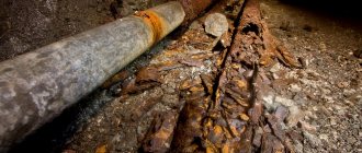
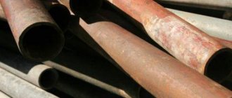
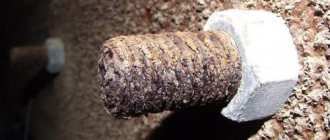
The service life of a pipeline is determined by the rate of corrosion. Destruction due to corrosive wear of utility networks entails financial losses and poses a threat to the environment, labor safety, and deteriorates the quality of the transported product. Critical elements of systems are susceptible to corrosion: control and shut-off devices.
The causes of pipeline corrosion are external and internal. The following types of negative impacts are considered environmental factors:
- Atmospheric;
- Soil-ground;
- Biocorrosion;
- Stray currents;
- Induced alternating currents.
Internal corrosion is caused by the chemical properties of the transferred substances, airing, and dynamic loads. The formation of sediment accelerates the process of changing the structure of the metal.
Corrosive destruction of equipment costs billions of rubles annually: inefficient operation, reduction in transported volumes, repair and maintenance costs, accidents. Pipeline corrosion control is carried out based on the standards of the Unified System of Protection against Corrosion and Aging (USZKS). The main regulatory document for underground structures is GOST 9.602-2016.
Types of pipeline corrosion
Iron reacts actively with oxygen only at a temperature of +260 Co. Such ranges are not supported in main lines, but an oxidative reaction can be triggered by moisture condensation in the insulating layer and microcracks of welds. This damage occurs when installation technologies are not followed and the service life is long.
Highways are characterized by electrochemical destruction mechanisms. In the chemical type, the metal interacts with the oxidizing agent without access to moisture. With electrochemical, moisture is present, and water, with salts dissolved in it, serves as an electrolyte.
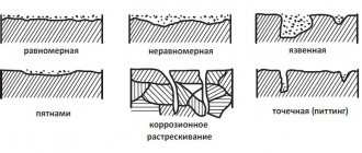
It is customary to distinguish between two types of corrosion damage:
- General: distributed evenly, calculated during design;
- Local: appear under the influence of the active environment and tensile loads.
Types of local destruction:
- Ulcerative: grooves on the outside, usually shallow in depth.
- Pitting: point lesions with great depth;
- Slotted: appear in the connecting gaps of parts, develop quickly;
- Cracks: grow slowly until they reach a critical value, then quickly lead to an accident.
For oil and gas industry lines, microbial contamination poses an additional threat. The most dangerous are sulfate-reducing bacteria that produce sulfates, sulfites and large amounts of hydrogen sulfide. The formation of biofilms leads to peeling of protective coatings.
To answer this question in detail, you will need to write a large article or even a book. The European Federation of Corrosion (EFC) Publication No. 23, Carbon Acid Corrosion in Oil and Gas Engineering, is an excellent source of information, although it is dated 1997. For more up-to-date information and practical recommendations, you can review recently published papers on this topic presented at the annual conferences of the International Association of Corrosion Engineers (NACE).
However, it is useful to consider this issue in two stages. For a given set of conditions, firstly, what is the probability of carbon dioxide corrosion occurring; and, secondly, if there is a probability, then in what form and at what speed will it occur.
While predictive models have become a very common tool, especially as the computing and technical capabilities of laptops, tablets and smartphones rapidly increase along with easy access to the Internet, I recommend stopping and thinking about what simple rules are worth having at hand. Regarding the likelihood of carbon dioxide corrosion occurring, the following rule of thumb is worth considering:
PCO2 < 7 psi (0.5 bar) Corrosion unlikely
7 psi (0.5 bar) < PCO2 < 30 psi (2 bar) Corrosion possible
PCO2 > 30 psi (2 bar) Corrosion
An important caveat to this rule is how the corrosion process is affected by the following partial pressure relationships, taking into account the presence of H2S:
CO2/H2S > 500 CO2 predominates
500 > CO2/H2S > 20 CO2/H2S mixture
0 > CO2/H2S > 0.05 H2S predominates
From a system design and operation perspective, and to develop a suitable corrosion/integrity management strategy, it is clear that the above guidelines provide a limited, rigid assessment and basis for operation. However, they allow a quick and easy analysis of the situation before starting modeling, which, despite everything, is necessary, but also has its problems and limitations.
There is no generally accepted and industry-accepted standard model of carbon dioxide corrosion. There has been a steady increase in the number of models in use over the years, driven in part by some large oil and gas companies developing their own models. Basically, all models are aimed at predicting carbon dioxide corrosion of carbon and low-alloy steels.
It is also worth noting here the long-term work of De Waard et al (Shell) for their significant contribution to understanding the principles and basic requirements of constructing a reliable carbon dioxide corrosion model and its reasonable application. Most of the 17 models readily found on the internet/published technical papers are largely based on the fundamental and practical understanding gained from the work of De Waard et al. It should be noted that many models are essentially empirical and based on laboratory and/or field data. The most comprehensive and widely accepted theoretically driven carbon dioxide corrosion model, a product of the Ohio State University-funded Inter-Industry Project (JIP) program, is an integral part of Ohio State's Multicorp corrosion prediction software, which covers nearly all key aspects of internal corrosion of mild steel oil and gas pipelines. If you are not an Ohio JIP member, there is a fee to access the Mulitcorp program.
Access to models may be limited, but as a starting point on the Internet you can find: carbon dioxide corrosion rate calculation model, NORSOK standard M-506 rev. 2, June 2005 Commercial models available for purchase: Electronic Corrosion Engineer's Tool ECETM ® (Wood Group) for quantifying corrosion rates, including carbon dioxide corrosion modeling and prediction, and selecting corrosion-resistant materials; and the proprietary enpICDATM carbon dioxide corrosion web model (Broadsword Engineering) is provided as part of the company's technical services.
A comparative review of many of the models was presented in paper #10371 at the 2010 NACE San Antonio Conference, Carbon Dioxide Corrosion Models for Oil and Gas Systems. Paper No. 05552 presented at NACE 2005, Houston, entitled “Carbon Dioxide Corrosion Prediction Tools. When can you trust them? provides additional reference material derived from BP's development of the Cassandra model.
All models have their own advantages and disadvantages, which will depend to varying degrees on the specific application. It would therefore be inappropriate to recommend the use of any one model here. Understanding the current situation and the technical features of the system is an extremely important step towards the correct selection and subsequent application of the model. The following key points need to be considered:
- Understanding the origins of the model and how it accounts for the key factors that will determine the predicted corrosion rate;
- range of partial pressure and temperature;
- how pH and range of applicability are calculated;
- flow mode and fluid velocity, taking into account that carbon dioxide corrosion is a controlled mass transfer reaction;
- the presence of potential corrosion hotspots, such as bends, blind branches, and surface flow disturbances, such as pre-existing corrosion, weld bead, can significantly influence the type of exposure (general or localized metal loss);
- surface contamination/shielding due to wax, scale, particulates can significantly affect the type of impact (general or localized metal loss);
- influence of wetting by the liquid hydrocarbon phase;
- The formation of protective FeCO3 scale, its nature and stability can significantly affect the type of impact (general or localized metal loss).
Additionally
- Presence of H2S – often results in very low overall corrosion rates but an increased risk of pitting corrosion, few models are able to predict combined corrosive action and corrosion rates in the presence of CO2 + H2S.
- The presence of dissolved volatile organic acids (eg acetic acid/acetate) can significantly increase the actual corrosion rate.
- Risk of corrosion at the top of the pipe (usually in wet gas systems, but can also occur in multiphase systems with stratified gas space flow) where the rate of moisture condensation is important; in addition, the risk is increased in the presence of volatile organic acids and H2S.
- The presence of particulate matter causing erosion-corrosion typically increases the impact on metal loss rates for carbon/low alloy steels, which can result in localized effects.
If these recommendations are taken into account when choosing a model, which can then be compared with field analogues, as a rule, it is possible to obtain acceptable predicted indicators, for example, carbon steel can be used with or without a corrosion inhibitor, taking into account a given corrosion allowance when calculating the required nominal wall thickness pipeline. In addition, the predicted performance can be used to assess corrosion risks when developing a corrosion control strategy. For example, if, based on the above points or test results, the impact is expected to be localized, a conversion factor (2 or 3) is typically applied to the predicted initial corrosion rate. Based on guidance documents and practical experience of companies, specific requirements for the applicable conversion factors can be specified. It is also important to understand that ineffective application of corrosion control techniques, such as inhibitor treatment and achieving the required system cleanliness, can negatively affect the initial value of the predicted corrosion rate.
It is not recommended to control corrosion solely on the basis of predicted corrosion rates once the system is put into service, no matter how good the model is considered to be. Modeling should be considered as a complement to a proactive and robust corrosion monitoring and control program with feedback to further improve the model.
And finally, can any model really predict the corrosion rate (mm/yr) to two or even one decimal place? The model can show the calculated speed with such accuracy, but this will depend more on the software than on the actual accuracy of the model. Caution should be exercised in using model-based predicted corrosion rates with such precision!
Don Harrop
, FICorr(Hon) FEFC(Hon), CorroDon Consulting Ltd.
Protection of main pipelines from corrosion
To increase the service life of highway elements, a set of measures is provided that corresponds to various types of negative impacts. During installation, drainage is provided and connections are insulated depending on the grade of steel. Active methods of protecting pipelines from corrosion are constantly being developed: reducing the aggressiveness of the environment, treating gas and oil pipelines with bactericides, and introducing inhibitor substances.
Protective coatings for pipelines against corrosion play an important role. Treatment with chemical compounds reduces the electrochemical effect and prevents the formation of point processes in microcracks. In addition, the internal surface and reinforcement remain smooth and prevent the formation of sediment. Industrial industry standards regulate the properties of coatings depending on the characteristics of the transported medium.
General provisions
Corrosion processes are the oxidation of a metal, in which its atoms change from a free state, losing their electrons, to an ionic state . An underground pipeline is subject to two types of corrosion, the nature of which is worth understanding before starting to deal with them. Therefore, I will pay a little attention to their description:
Soil
Diagram showing the effects of soil corrosion on a metal pipeline
As you probably guessed from the name and the accompanying diagram, soil corrosion occurs due to contact of steel with soil. In turn, it is divided into the following subspecies:
- Chemical _ Appears as a result of exposure to iron by gases and non-electrolytes of the liquid type. It is noteworthy that with it the material is destroyed evenly, and the formation of through holes is almost impossible, which makes this type of corrosion process the least dangerous for a highway laid underground;
- Electrochemical . The metal acts as an electrode, and groundwater, of which there is an incredible amount in our climate zone, acts as an electrolyte. The ongoing process is very similar to the work of a galvanic couple and provokes the destruction of point areas on the surface of the pipes, which ultimately leads to their emergency condition;
The result of damage to the wall of a steel pipe by electromechanical corrosion
- Electric . It occurs due to the impact of stray currents on steel, which can “drain” from rails, substations and other electrified devices that fill modern cities. It is the most dangerous and destructive corrosion process.
Internal corrosion
Diagram showing the effects of internal corrosion on a metal pipeline
If the transported liquid has a low hydrogen index, but its content of oxygen, sulfates and chlorides, on the contrary, is high, then internal corrosion processes cannot be avoided, as a result of which:
- The level of roughness of the inner surface of the wall increases , which leads to a decrease in water permeability;
The inside of the pipeline becomes rougher due to the effects of internal corrosion
- The quality of the transported liquid deteriorates as rust gets into it;
- Over time, a through hole may appear , which can cause a pipeline rupture.
Types of protection
Today, there are several different methods for treating underground heating pipes from rust and corrosion. All of them are based on the principle of special processing, during which the metal from which the tanks are made reacts with the introduced substances and solutions. As a result of such actions, a special film is formed, which provides protection.
There are several main types of anti-corrosion protection methods:
- processing liquids using chemical reagents;
- wall treatment;
- stray current;
- cathode;
- anodic
Liquid handling
The liquid that flows through the pipeline may have some aggressive qualities. The aggressive composition of water can be a consequence of the content of carbonates, bicarbonates or oxygen in it, which causes the metal to become covered with rust.
It is technically quite difficult to perform high-quality cleaning of the walls of underground pipes or to clean them completely. The main task of chemical water treatment is to transform its composition from aggressive to weakly calcifying. This treatment of underground heating pipes for rust often comes down to adding soda, calcium or sodium carbonate to the water.
In those sections of water pipelines in which water can be distributed to individual water intake points, its further processing is carried out by adding polyphosphates.
Anti-corrosion protection of galvanized underground tanks is carried out by adding silicates, phosphates and polycarbonates. Thus, a special film appears on the inner surface of galvanized pipes, preventing corrosion.
Wall treatment
Wall treatments have been used to protect against corrosion for many years. To carry out this set of measures, the coating is applied to the outer or inner wall of the underground pipe.
Thanks to galvanization, an active or passive film of high strength is formed on the surface, which does not allow the aggressive environment to penetrate into the deep layers of the metal. The effect of such actions can easily persist for a fairly long period.
Typically, another metal is applied to the surface of the product. Most often, zinc is used for this, which is not affected by corrosion. Paint, varnish or enamel can be applied to the metal surface, which also act as an effective treatment for gas pipelines.
To achieve maximum effect when fighting rust, alloys of metals such as zinc or magnesium are often used. Experts say that galvanizing pipes is the most popular of all processing methods existing today.
Stray current
Stray current is a current that is formed in soils during the dispersion of electrified paths. Energy enters a point that is the cathode and exits at a point that is the anode.
During the process, electrolysis occurs, which can cause rust and damage to the tank. In this case, the anti-corrosion insulation of underground pipelines is electrical drainage.
Low resistance cables are connected to the current source at specially designated locations.
Induced current
Cathodic anti-corrosion protection of underground tanks is based on the use of electric current, which is supplied in a constant mode and prevents the metal protection film from being destroyed.
This method is carried out by using a cable with low electrical resistance, but with excellent insulation. In this case, the pipeline itself acts as a cathode and is thus protected from possible corrosion processes.
Sacrificial anode
Another fairly effective type of protection against stray currents is anodic chemical protection. A buried magnesium block acts as an anode in a corrosive environment. Thanks to the slow decomposition of magnesium, main steel pipelines are insulated from underground stray currents. This type of protection is most often used to protect products of limited length or for tanks made of steel.
Typically, the anode is placed in a cotton or jute bag, which in turn is immersed in the clay mixture. The main objective of such packaging is to ensure uniform consumption of the anode, as well as maintaining the required level of humidity.
This system will prevent the formation of a film, which could hinder the decomposition of the anode.
It can be noted that the best way to protect the internal and external surfaces of pipes from the occurrence of corrosive processes is to use materials that are least susceptible to them. And, nevertheless, even on such materials, for certain reasons, pockets of corrosion and damage of various kinds can occur. And therefore, it is best to use one of the most suitable protection methods currently used during the process of using pipes.
2.1. Causes of corrosion on the outer surface of metal
2.1.1. Corrosion of the outer surface of the metal of pipelines occurs when moisture is present directly on the surface of the metal. The intensity of this corrosion is determined by the following:
temperature (the corrosion rate increases with increasing temperature to 70 - 80 ° C);
composition of insulating materials, including thermal insulation;
presence of stray currents*;
salt composition, total acidity, alkalinity, pH value of soil-ground electrolyte and composition of soil-ground air*;
specific electrical resistivity of soils and soils*
* These factors play a significant role in ductless installation of heat pipelines, as well as in areas of duct installation prone to flooding or silting.
the level of local mechanical stresses in the metal;
participation of microorganisms (biocorrosion).
2.1.2. The most dangerous is corrosion by stray currents (electrocorrosion), which occurs in the case of a positive or alternating potential difference between the heating network pipeline and the ground. Sources of stray currents are:
rails of DC-electrified trams, railways, subways, and mine transport;
anodic grounding of electrochemical protection installations on adjacent underground structures;
pipelines with electrochemical protection;
grounding of DC power lines using the “wire-ground” system;
galvanic baths and welding installations with current leakage into the ground;
electrical interference from power cables when laying communications in a common manifold.
3.3. Typical cases of internal surface corrosion
In connection with the localization of internal surface corrosion, typical cases of its manifestation can be identified.
3.3.1. Ulcers or fistulas on pipelines (Figure 4), not associated with construction and installation work during new construction and repairs, the occurrence of which is determined by the heterogeneity of oxide films on the metal and the metal itself.
3.3.2. Corrosion in the slot of technological lack of penetration of the weld. Basically, lack of penetration occurs at installation joints, but sometimes also on straight-seam pipes of small diameter (DN = 150 mm) in factory joints made by contact welding.
Figure 6 — View of the pipeline wall during the formation of a fistula from internal corrosion and the subsequent development of external corrosion
- fistula
- humidification zone
3.3.3 Corrosion pits and grooves in the heat-affected zone of factory and installation welds (Figure 7). This is due to the formation of an iron oxide film on the metal surface near the seam, which has a structure different from the film on the rest of the surface.
3.3.4 Corrosion pits and grooves on the lower generatrix of the pipe (Figure 8). Associated with sludge corrosion due to high aggressiveness of supply water.
3.3.5 Corrosive destruction of the metal of repair patches in conical transitions from one diameter to another made on the installation site. Corrosion is associated with differences in the composition of the carbon steels used and mechanical stresses.
3.3.6 Corrosion pits and grooves in the place where the supports are welded to the pipe (Figure 9). Corrosion is associated with heating of the inner surface of the pipe metal during welding of supports and high mechanical stresses.
3.3.7 Complete destruction in the form of a field of ulcers merging with one another. It is typical for places with low fluid velocity (bypasses, bends, fittings), and sometimes also for the head sections of main pipelines.
Figure 7 — Groove in the metal from internal corrosion near the factory seam
Figure 8 — View of the corrosion groove along the lower generatrix of the pipeline DN = 1000 mm
Figure 9 — Destruction of the pipe metal from internal corrosion at the welding site of the support (pipe DN = 200 mm)
Corrosion by sour oil
represents a more serious problem associated with the oil and gas industry. While carbon dioxide corrosion involves a slow, localized loss of metal, sour oil corrosion can lead to the formation of cracks. These damages are difficult to spot early and monitor closely, and can lead to a catastrophic and – quite possibly – dangerous accident. Thus, the primary goal is to identify the risk at the design stage and select materials that are not prone to cracking, rather than controlling the situation with corrosion inhibitors.
Causes
Pipeline rust is the process of destruction of a metal structure during a chemical reaction of oxidation of metal surfaces with a liquid.
The result of this reaction is a change in the structure of the metal at the ionic level, from which the product becomes covered with a harmful substance and disintegrates or completely disappears from the surface.
Before using a metal structure, it is necessary to analyze the environment of use and the nature of the liquid in order to determine the methods of combating it, otherwise welding work must be used to remove traces of damage.
2.2. Appearance and main signs of corrosion damage
2.2.1. Corrosion of the outer surface of pipelines is characterized by the spread of the damage area over a significant surface - 0.5 - 1.5 m or more along the length of the pipe.
The spread of corrosion along the perimeter of the pipe is determined by the cause of wetting of the outer surface of the pipe (drops from above, flooding, etc.).
2.2.2. The surface of a corroded pipe is covered with a film of corrosion products, which has a layered structure. These layers are weakly adhered to each other and to the metal and peel off quite easily.
Under the lower layer of corrosion products, the surface is lumpy (Figure).
2.2.3. The main sign of corrosion starting on the outer surface is the thinning of the rupture edge and the pipe surface surrounding the edge to 0.5 - 1 mm (Fig. 2a). The pipeline may also have metal damage from corrosion on the internal surface, but the pits from internal corrosion do not coincide with the line of metal rupture (Figure 1).
2.2.4. When exposed to stray currents, fistulas with smooth walls and a crater facing outward (Figure 2b), usually free of corrosion products, can form on the outer surface.
