What it is
Fluorescent paints are special compounds that, under the influence of ultraviolet light, make any image more voluminous and impressive. The coating base consists of a set of pigments that accumulate and reflect light. They are connected to each other with an adhesive transparent base, which allows you to fix the composition on the surface.
Surfaces painted with fluorescent paint look great at night, decorating the room and creating a special atmosphere.
Fluorescent paint
What properties does it have?
The main property of fluorescent paints is luminescence. This term refers to the process of accumulation of light energy during the day with the subsequent release of light at night.
At the same time, fluorescent coatings are more adapted not to the accumulation of light, but to its reflection with an increase in overall brightness and volume. As a result, it is possible to achieve a unique effect that turns even boring gray rooms into real works of art.
The paints contain a special pigment that gives the painted surface an acidic richness. A wide range of colors allows you to choose a shade for each specific occasion.
The dyes are safe, non-toxic and environmentally friendly, so there are no restrictions on their use inside living rooms.
Fluorescence Microscopy (Part 1)
Introduction to Fluorescence Microscopy
The absorption and subsequent re-emission of light by organic and inorganic samples usually results from a common physical phenomenon called either fluorescence or phosphorescence. The emission of light by fluorescence occurs almost simultaneously with the absorption of exciting light, due to the relatively short delay time between absorption and emission of a photon, which usually does not exceed a microsecond interval. When there is a longer interval between the absorption and emission of light, this phenomenon is called phosphorescence.
Rice. 1. Epi-fluorescence microscope
Fluorescence was first described in 1852 by the British scientist George Stokes, who coined the term while conducting experiments with fluorite (fluorspar), which emits red light when irradiated with ultraviolet light. Stokes noticed that the wavelength of fluorescent emission is always greater than the wavelength of excitation light. Early research in the 19th century showed that many samples (including minerals, crystals, resins, medicinal raw materials, oils, chlorophyll, vitamins and inorganic compounds) fluoresce when irradiated with ultraviolet light. However, the use of fluorochromes in biological research to stain tissue components, bacteria and other pathogens did not begin until the 1930s. Some of these dyes were extremely specific and stimulated the development of fluorescence microscopy.
Due to several features that are difficult to achieve with traditional contrast-enhanced optical microscopy, fluorescence microscopy has become an important tool in both biological and biomedical research and materials science. The use of sets of fluorochromes has made it possible to isolate highly specific cells and submicroscopic cellular components from non-fluorescent substances. With a fluorescence microscope, in fact, even individual molecules can be detected. Using fluorescent multistaining, different dyes can identify multiple target molecules simultaneously. Although the spatial resolution of a fluorescence microscope is limited below by the diffraction limit, which depends on the specific characteristics of the sample, detection of fluorescent molecules below this limit is quite possible.
Many samples exhibit autofluorescence when irradiated (without the use of fluorochromes), and this phenomenon is widely used in botany, petrology, and the semiconductor industry. In contrast, the study of tissues of animals or pathogens is often complicated by either extremely weak or, conversely, strong nonspecific autofluorescence. Much more important in this case is the introduction into tissues of fluorochromes (or fluorophores), excited at a certain wavelength and emitting light with the required intensity. Fluorochromes are dyes that, independently attaching to visible or invisible structures, have high selectivity towards targets and a high quantum yield (the ratio of the number of emitted to the number of absorbed photons). The rapid growth in the use of fluorescence microscopy is closely related to the emergence of new synthetic and natural fluorophores that have specific excitation and emission intensity profiles and are “targeted” at given biological targets.
Basics of excitation and emission processes
The principle of operation of a fluorescence microscope is to irradiate a sample at wavelengths in the required and precisely defined range, followed by the separation of much weaker emitted fluorescence from the flow of exciting light. In a well-tuned microscope, only the emitted light should reach the eye or receiving device, so that the observed fluorescent structures are superimposed on a high-contrast, very dark (or black) background. The darkness of the background generally determines the detection limits, since the excitation light is typically hundreds of thousands, or even millions, of times brighter than the emitted fluorescence.
Figure 1 shows a schematic cross-section of a modern epifluorescence microscope, designed for observations in both transmitted and reflected light. The vertical illuminator, located in the center, has a light source at one end (indicated in the diagram as an episcopic module) and a filter attachment at the other. The design is based on a microscope that operates in reflected light, the wavelength of which is greater than the excitation wavelength. The author of the vertical illuminator for reflected light fluorescence microscopy is considered to be Johan S. Ploem. Multi-frequency light from an arc lamp or other source, passing through a selective excitation filter, is converted in a fluorescent vertical illuminator into light with a certain wavelength (or in a given wave interval), usually from the ultraviolet, blue or green parts of the spectrum. The flux passed through the excitation filter is reflected from the surface of a dichromatic (also called dichroic) mirror or beam splitter and, passing through the objective, illuminates the sample with intense light. If the sample fluoresces, the emitted light, collected by the objective, again passes through the dichroic mirror and is then filtered by a blocking (or emission) filter, which blocks light at excitation wavelengths. It is important to note that fluorescence is the only mode in optical microscopy in which the sample emits its own light after irradiation. The emitted light is re-emitted spherically in all directions, regardless of the location of the irradiating light source.
Epifluorescence illumination is the predominant method in modern microscopy. The vertical reflected light illuminator is located between the observation tubes and the revolving head of the lenses. The illuminator is designed in such a way that the excitation light on the way to the image and from the sample passes through the same microscope objective, which in this configuration first acts as a condenser, and on the return path collects the emitted fluorescence light. Lighters of this type have several advantages. The lens of a fluorescence microscope acts, firstly, as a well-tuned condenser, and secondly, as a light-collecting device with which an image is formed. Being the same component, the lens/condenser is always perfectly aligned. Most of the excitation light reaching the sample passes through it without interaction and does not return to the objective, and the illuminated area is limited to that part of the sample that is observed through the eyepieces (in most cases). If the microscope is properly configured for Köller illumination, then, unlike some contrast-enhancing techniques, the full numerical aperture of the objective lens is available for observation. In addition, it allows you to combine the observation modes in transmitted and reflected light, the digital image formation mode, or select one of them.
Rice. 2. Fluorescent filters
As shown in Figure 1, at the rear end of the vertical reflected light illuminator is an arc lamp unit (usually mercury or xenon). Propagating along the illuminator perpendicular to the optical axis of the microscope, the excitation light passes through the collecting lenses, the adjustable and centered aperture diaphragm, and then through the adjustable centered field diaphragm (see Figure 1). After this, the light enters the excitation filter, where wavelengths are selected from the required interval and the remaining wavelengths are blocked. After passing through the excitation filter, the selected wavelengths reach the dichroic beam splitting mirror, which is a special interference filter that effectively reflects short-wavelength light and effectively transmits long-wavelength light. The dichroic beam splitter is tilted at an angle of 45 degrees with respect to the incident excitation light and reflects it at an angle of 90 degrees through the optical system lens directly onto the sample. The fluorescence emitted by the illuminated sample is collected by the lens, which now performs its usual function, namely image formation. Since the emitted wavelengths are longer than the excitation wavelengths, they pass through the dichroic mirror upward to the observation tubes or electron detector.
Most of the scattered excitation light reaching the dichroic mirror is reflected back to the light source, although a small fraction may pass through or be absorbed by the internal coating of the mirror. But before the emitted fluorescence reaches the eyepiece or detector, it must pass through a blocking or rejection filter. These filters block (block) any residual excitation light, but allow longer wavelengths of emitted light to pass through. Most reflected light illuminators combine the excitation filter, dichroic mirror, and stop filter into an optical unit (often called a cube), as shown in Figure 2. Modern fluorescence microscopes can accommodate four to six filter cubes (usually on a carousel or drawer type attachment). ; see Figure 1) and allow the user to easily install replaceable excitation filters, blocking filters and dichroic mirrors.
The vertical illuminator design should allow the user to adjust the microscope for Köller illumination, which provides bright and uniform illumination across the entire field of view. Corrected condenser lenses of the optical system ensure that the image of the centered aperture diaphragm is aligned with the rear aperture of the focusing lens. In modern illuminators, the image of a pre-focused, centered field diaphragm is conjugate with the focused image and plane of the fixed diaphragm of the eyepiece.
The illuminator lamp unit usually contains a stop filter that blocks infrared light. The lamp unit itself should not transmit ultraviolet radiation to the outside. It is also desirable that it has a built-in circuit breaker in case it opens during operation. The lamp unit must be strong enough to withstand the possible explosion of the arc lamp during operation. In modern lamp units, the lamp socket is equipped with adjustment knobs to center the arc lamp image in the rear aperture of the lens (under Keller illumination, these planes are conjugate). It is advisable to place a shutter in the light path, usually close to the lamp unit but before the excitation filter, to completely block the excitation light unless the sample is being observed. In addition, the equipment of the illuminator must include neutral density filters (on a drum, carousel or retractable type attachment) in order to be able to reduce the intensity of the exciting lighting.
Stokes shift
When electrons transition from the excited to the ground state, vibrational energy is lost. As a result of this loss of energy, the emission spectrum of the excited fluorophore usually shifts toward longer wavelengths compared to the absorption or excitation spectrum (remember that wavelength is inversely proportional to its energy). This well-known phenomenon is called Stokes' rule or Stokes shift. As the Stokes shift increases, it becomes easier to separate excitation and emission light using fluorescent filter combinations.
The peak emission intensity of a fluorophore is usually lower than the peak intensity of its absorption and occurs at a longer wavelength. The emission curve (spectral curve) is often a mirror image (or close to it) of the excitation curve, but shifted towards longer wavelengths, as shown in Figure 3, which shows the useful spectral characteristics of the Alexa Fluor 555 dye, which absorbs in the yellow-green , and emits in the yellow-orange region. To achieve maximum fluorescence intensity, the fluorophore (often called a dye) is excited at wavelengths close to or near the peak of the excitation curve, and the emitted light is detected over the widest possible range that includes the emission peak. The selection of exciting and emitted wavelengths is carried out using interference filters (Figure 2). In addition, it should be noted that the spectral characteristics of the microscope's optical system also depend on the transmittance of the glass (which is affected by antireflective coatings), the number of lenses and mirrors, and the sensitivity of the detectors.
Rice. 3. Fluorophore absorption and emission curves
The efficiency of separating and recording excitation and emission wavelengths is achieved in fluorescence microscopy by the correct choice of light filters that block or, conversely, transmit light of certain wavelengths in the ultraviolet, visible and near-infrared regions of the spectrum. Excitation light is controlled in vertical fluorescent illuminators due to the fact that their design provides for the use of easily replaceable filters (neutral and interference excitation filters) inserted along the light path to the sample and on the return path between the sample and the observation tubes or signal reception system. Due to the low intensity of fluorescent emission (as discussed above), it is necessary that the excitation light source has sufficient brightness to maximize the weak emitted light, and that the fluorochromes have appropriate absorption characteristics and quantum efficiency. This is perhaps the key criteria for fluorescence microscopy.
The efficiency at which an individual fluorophore absorbs a photon of excitation light is a function of the effective molecular cross section, and the probability of such an event occurring is called the absorption coefficient. Larger values of the absorption coefficient indicate that absorption of a photon (or quantum) in a given wavelength interval is more likely. Quantum yield is the ratio of the number of emitted to the number of absorbed quanta (usually it lies in the range from 0.1 to 1.0). The fact that the quantum yield takes values less than 1 is a consequence of energy loss in a non-radiative manner, for example through heat or a photochemical reaction, when re-emission does not occur, leading to fluorescence. Absorption coefficient, quantum yield, average luminous intensity, and exposure time are important factors affecting the fluorescence intensity and determining the feasibility of using this method.
Fading, fading and photobleaching
A number of conditions can affect the likelihood of fluorescence re-emission, often leading to a drop in fluorescence intensity. The general term for a decrease in the intensity of fluorescent emission is fading, covering all phenomena, which for more detailed description can be divided into the phenomena of quenching and photobleaching. Photobleaching is the irreversible decay of fluorescent molecules in an excited state, caused by their interaction with molecular oxygen before emission. This phenomenon is used in the fluorescence recovery after photobleaching (FRAP) method, which is very effective in studying the diffusion properties and movement of biological macromolecules. The method is based on photobleaching with a laser beam of a clearly defined area in the sample, followed by observation of the rate and nature of fluorescence recovery in the photobleached area. A related technique, fluorescence decay in bleached images (FLIP), is used to study the decrease in fluorescence in regions adjacent to the photobleached region. Like FRAP, this method is an effective tool for studying molecular mobility and dynamics in living cells.
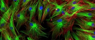
Rice. 4. Rate of photobleaching of multicolored samples
Figure 4 shows a typical example of photobleaching observed in a series of digital images of a multistained culture of Indian muntjac skin fibroblasts taken at different time points. Nuclei were stained with bis-benzimidazole derivative (Hoechst 33258, blue fluorescence), and mitochondria and actin cytoskeleton were stained with MitoTracker Red CMXRos (red fluorescence) and phalloidin derivative coupled to Alexa Fluor 488 (green fluorescence), respectively. Images were taken every two minutes, and the combination of fluorescent filters was adjusted so that all three fluorophores were excited simultaneously, while simultaneously recording the combined emitted signals. Figure 4(a) shows that the intensity of all three fluorophores is relatively high, but the Hoechst intensity (blue) begins to fall rapidly after just two minutes and is almost completely gone after 6–8 minutes. Mitochondrial and actin dyes appear to be more resistant to photobleaching, but their intensity also decreases significantly during the observation period (10 minutes).
Relaxation from the excited state by quenching, leading to a drop in fluorescence intensity, occurs in a variety of non-radiative ways and is often due to oxidizing agents or the presence of salts, heavy metals and halogen compounds. In some cases, quenching occurs as a result of the transfer of energy to another molecule (called an acceptor) that is close to the excited fluorophore (donor). This phenomenon is called fluorescence resonance energy transfer (FRET). It is this mechanism that has become the basis for an effective method for studying molecular interactions and associations at distances significantly smaller than the resolution of optical microscopes.
Fluorescent light sources
An unfortunate consequence of low emission intensity in most fluorescence microscopy applications is the low number of photons reaching the eyepiece or receiver. In most cases, photon collection efficiency in optical microscopes is less than 30 percent, and the concentrations of many fluorophores along the optical path range from micromolar to nanomolar concentrations. To ensure that the excitation light intensity is sufficient to detect fluorescence, powerful compact light sources, such as small high-energy arc lamps, are needed. The most common are mercury lamps with a power of 50 to 200 watts and xenon lamps with a power of 75 to 150 watts (see Figure 5). These lamps are typically powered by an external DC source sufficient to ignite the arc through high pressure vapor ionization and keep it burning with minimal flicker.
The microscope's external arc lamp power supply is usually equipped with a timer to track the number of hours worked. Arc lamps lose luminous output and often break down when used beyond their specified service life (200–300 hours). Mercury lamps do not provide uniform intensity across the spectral range from UV to IR. Their maximum intensity occurs in the near ultraviolet. Distinct intensity peaks occur at 313, 334, 365, 406, 435, 546 and 578 nanometers. At other wavelengths in the visible spectrum, the intensity is stable, although not as high (but still sufficient for most applications). But lamp power in itself is not a determining parameter for lighting efficiency. Conversely, an essential parameter that must first be taken into account is the average luminosity, taking into account the brightness of the source, the geometry of the arc and the angular distribution of the radiation.
Rice. 5. Arc fluorescent lamps
In the last few years, optical microscopy has experienced an upsurge in the use of laser light sources, especially argon ion and argon-krypton (ion) lasers. The advantages of these lasers are their small size, low beam divergence, high degree of monochromaticity and high average luminosity. They are widely used in scanning confocal microscopy, which has become a powerful tool for creating high-contrast fluorescent images by eliminating out-of-focus light coming from the focal plane of the sample. In confocal microscopes, this is achieved by scanning the sample with a focal point or line while simultaneously forming an image through a conjugate aperture. Optical sections of samples can be stored in the microscope's computer memory and reconstructed into a final image displayed on a monitor.
Filter symbols
The general terminology adopted to refer to filter combinations in fluorescence microscopy has become quite confusing due to the different abbreviations and codes used by different manufacturers to label their filters. In principle, there are three main categories of filters: excitation filters (often simply called exciters), blocking (emission) filters, and dichroic beam splitters (or dichroic mirrors). Previously, fluorescent filters consisted solely of colored glass or gelatin sandwiched between two glass plates. However, today there is a tendency to produce highly sensitive filters with interference optics for transmitting or delaying light of strictly defined wavelengths, which also has a high transmittance. Dichroic beam splitters are special interference filters designed to reflect or transmit light of specific wavelengths when placed at a 45-degree angle along the light path (see Figures 1 and 2). Blocking filters are made from either colored glass or interference coatings (or a combination of both).
Manufacturers use different abbreviations to indicate the characteristics of excitation filters. Ultraviolet glass, for example, is designated UG, and blue glass is BG. On narrowband filters you can often find the designation KP (K from the German “kurz”, which translates as “short”) or simply SP. Interference filters are now labeled by some manufacturers with the abbreviation IF. Narrowband interference excitation filters are especially effective at low Stokes shifts.
Abbreviations and abbreviations for blocking filters are as follows: LP or L for broadband filters, Y or GG for yellow (from the German "gelb" - yellow) glass, R or RG for red glass, OG or O for orange glass, K for slot filters (from the German “kante” - edge), and BA for blocking filters. If a filter is labeled with a number, such as BA515, it indicates the wavelength (in nanometers) at which it has half its maximum transmittance.
Dichroic beam splitters are also labeled with different abbreviations: CBS stands for chromatic beam splitter, DM stands for dichroic mirror, TK stands for slot splitter (from the German “teiler kante”), FT stands for color splitter (from the German “farb teiler”), and RKP stands for narrowband reflector. All these designations are interchangeable; In addition, the optical glass of all modern dichroic beam splitters is always coated with interference coatings (rather than organic or metallic dyes). These thin interference films have high reflectance of short wavelengths and high transmittance of long wavelengths. The dichroic beam splitters are tilted at a 45 degree angle with respect to the excitation light incident on the optical block through the reflected light fluorescent illuminator. Their main function is to redirect certain (shorter) exciting waves to the objective and to the sample located behind it. These special filters also have the additional function of passing longer fluorescence wavelengths to the blocking filter and reflecting the scattered excitation light back toward the lamp unit.
Rice. 6. Nikon B-2E mid-band blue excitation filter
Figure 6 shows transmission curves for a combination of typical fluorescent filters used in modern microscopes. The excitation filter spectrum (red curve) shows high transmittance (approximately 75 percent) in the range of 450 to 490 nanometers with a center wavelength (CWL) of 470 nanometers. The dichroic mirror (yellow curve) reflects waves in the spectral range of the excitation filter, but transmits, with a relatively high coefficient, shorter and longer waves. It should be noted that zero transmission of a dichroic mirror corresponds to 100 percent reflection. The distinct dip in the transmittance curve between 450 and 500 nanometers, which corresponds to the reflection peak, serves to redirect waves from the 90-degree excitation filter passband onto the sample. The last link in this sequence is the emission or blocking filter (white curve), which transmits waves in the green part of the visible spectrum in the range from 520 to 560 nanometers. To ensure almost complete separation of reflected and transmitted waves, the boundaries of the reflection and transmission bands of the various superimposed spectra must be as steep as possible. The sinusoidal part of the dichroic mirror spectrum curve, called the ringing, is the result of the thin film deposition process. The high efficiency of this filter combination is an example of significant advances in thin coating interference filter technology.
Nikon's naming conventions are based on mixed terms that emerged in the early 1990s. At that time, all of Nikon's additional filter combinations were produced using the hard coating method, but today many filters are manufactured using advanced soft coating methods. Although soft coatings are more sensitive to humidity and heat and require more careful handling (compared to hard coatings), they exhibit higher optical densities and provide greater ease in fine-tuning specific bandwidths. Understanding the conventions of Nikon filter combinations allows you to quickly select the necessary filters for specific fluorophores.
The first letter in Nikon's alphanumeric notation system indicates the region of the excitation spectrum (for example, UV, V, B, and G are abbreviations for the English words "ultraviolet" - ultraviolet, "violet" - violet, "blue" and “green” - green, respectively). The number following the excitation spectrum encoding indicates the bandwidth of the excitation filter: 1 corresponds to narrowband excitation, 2 to midband excitation, and 3 to broadband excitation. Finally, one or more letters following the number corresponding to the excitation bandwidth indicate the characteristics of the blocking filter. The letter A indicates the standard broadband cutoff filter with the lowest cutoff wavelength, B indicates the broadband cutoff filter having a higher cutoff wavelength. The designation E (from the English "enhanced" - enhanced) in bandpass emission filters indicates improved performance in the sense of reducing the interference interaction of the separated signals. The E/C designation indicates a combination of soft interference coatings designed specifically to work with specific dyes such as DAPI, FITC, TRITC and Texas Red.
Fluorescent light balance
Evaluating the light fluxes of a typical fluorescence microscope provides a general idea of the limitations that will inevitably arise when generating digital images or visually observing samples. The irradiation source for our evaluation will be a standard 75-watt xenon arc lamp, which has an average luminous flux density of approximately 400 candelas per square millimeter (other sources are presented in Table 1). When the emitted light is directed at a 490-nanometer interference filter (with a 10-nanometer bandwidth and 75 percent transmittance), about 2 milliwatts of lamp output will pass through it. After reflection from a dichroic mirror with a coefficient of 0.9, a luminous flux of 1.8 milliwatts is directed to the rear aperture of the microscope objective as an exciting beam.
For a 100x objective with a numerical aperture of 1.4, the illuminated area of the sample will be 12×10•E(-6) square centimeters, if the diameter of the field of view is assumed to be approximately 40 micrometers. Then the light flux incident on the sample will be about 150 watts per square centimeter, which corresponds to a flux density of 3.6×10•E(20) photons per square centimeter. Thus, the illumination intensity of the sample is approximately 1000 times greater than the illumination intensity of the earth's surface on a normal sunny day.
Fluorescent emission at such a luminous flux depends on the absorption and emission properties of the fluorophore, its concentration in the sample and the optical path length of the sample. The mathematically produced fluorescence (F) is described by the equation:
F = σ • Q • I
where σ is the molecular absorption cross section, Q is the quantum yield, and I is the incident light flux calculated above. Assuming that fluorescein is a fluorophore with an absorption cross section (σ) of 3×10•E(-16) square centimeters, we obtain a Q of 0.99, which results in a fluorescence F of 100,000 photons per second per molecule. At a dye concentration of 1 micromole per liter, uniformly distributed in a disk 40 micrometers in diameter and 10 micrometers thick (volume equal to 12 picolitres), this results in approximately 1.2×10•E(-17) moles of dye or 7.2 million molecules in the optical path. If all molecules are excited simultaneously, the fluorescence rate will be 7.2×10•E(11) photons per second (which is the product of F and the number of dye molecules). The question arises: how many emitted photons will be recorded, and how long can this emission rate continue?
Kinds
The following types of fluorescent paints are distinguished:
- Acrylic. Quick-drying, odorless, aqueous dispersion composition. It can be used in any room and is resistant to temperature changes and high humidity. Works well on plastic, metal, concrete and other materials.
- Enamel for interiors. Luminous finishing material used for painting interior spaces. Bonds tightly to drywall, wood or plaster.
- Ink. Composition for interior printing. Used on inkjet and laser printers of various formats. Allows you to get an original picture or inscription.
- Aerosol. Paint in cans based on alkydurethane or acrylic. Durable coating that is resistant to temperature changes, high humidity and prolonged exposure to sunlight. Used by artists to apply spectacular images to various surfaces.
- Powdery composition. Dry coloring components, often used as additives to standard coatings. They are used for finishing facades, creating path markings, as well as developing car aerodesign.
Application of fluorescent paint
Paint application technology
To create a coating on a wall or any other object, several important conditions must be met:
There should be no dust or moisture on the surface to be treated. Dark and black areas are pre-primed or painted white.
When a transparent dye is applied to a colored surface, the spectral transformation of the UV rays changes. To obtain an accurate color, the substrate is bleached.
There should be no dust or moisture on the surface to be treated.
Surface preparation
Before painting, the surface is washed, the old coating is removed, clean objects must be degreased using solvents, then washed and dried well so that no traces of moisture remain.
Before painting, the surface is washed, the old coating is removed, and clean objects must be degreased.
Coloring
Fluorescent paint or enamel is applied with a brush, spray gun or roller. To paint small objects of complex shape, use a sponge or cuvette. Thickened compositions are pre-diluted to the consistency of liquid sour cream. Before applying paintwork materials, be sure to mix them.
When using stencils, the borders are glued with masking tape. Two-layer coatings are applied in perpendicular directions.
Fluorescent paint or enamel is applied with a brush, spray gun or roller.
When choosing a coating, it is important to know exactly what the luminous paint is called. Traditional fluorescent bright green color goes well with yellow and orange. You can create compositions that glow in the UV spectrum on facades, bodies, and walls.
Scope of application
Fluorescent paints are used in the following industries:
- decorating walls and building facades;
- art;
- body art, including manicure and makeup;
- creation of designer clothes;
- painting fences;
- auto tuning and airbrushing on the car body;
- creating bright elements on workwear and road signs.
These are just the main areas of application of luminous compositions. They can also be seen on some household items, souvenirs and children's toys.
How is it different from fluorescent
Fluorescence is classified as a type of luminescence. The differences relate to how long the light is released. Phosphors are capable of glowing in the dark for 8-12 hours, without requiring additional energy recharge. Accumulation occurs during the day, while at night the coating only emits light.
Fluorescent compounds are directly dependent on exposure to ultraviolet rays. In this case, intense exposure to sunlight leads to pigment fading and a decrease in the brightness of the glow. They do not so much glow themselves as they reflect the UV spectrum.
Fluorescent paint is an extremely effective and bright coating, the use of which allows you to get an impressive result. Understanding the features of such paints will protect you from surprises and help you achieve your goals in interior design or other areas in the shortest possible time.
How to make it yourself
Having found out how much the finished composition costs, many people make the fluorescent dye themselves. To do this, purchase a pigment with a reflective effect and add powder to acrylic varnish. A fluorophore is a substance with a polymer base; the pigment can be purchased online or in specialized stores for artists.
It is better to immediately select the powder of the desired color, so as not to add additional color to the varnish.
The fluorophore is poured into a glass or porcelain container, filled with acrylic varnish, and mixed well until the composition is homogeneous. The reflectivity of the paint depends on the amount of filler; the minimum amount is up to 10%, the maximum is ½ the volume of varnish. Before use, the finished mixture must be stirred well each time so that the fluorophore that has settled in the sediment rises to the top.
The thickened varnish is first diluted with water.
It is better to immediately select the powder of the desired color, so as not to add additional color to the varnish.